The Battery - Part 1
The E-Hawk battery pack is comprised of 560 18650 cells. The pack is made up of 28 modules in series, with each module having 20 cells in parallel (28S20P). Using bus bars the modules will be connected in series and housed in an aluminum enclosure with active air cooling. When complete, the pack will employ a main disconnect, contactor, fuse, DC-DC converter, temperature sensors, and maybe a BMS. The nominal capacity will be just over 5kWh.
We decided on the Sony VTC6 cells as they exhibit a good mix of energy density and power density. We were also able to get a good price on the cells. The photos below document our design and build process.
Disclaimer: All of the photos included in this blog posting reflect work that was completed prior to the covid-19 pandemic.

Workers demonstrate contentment early in the battery pack fabrication process.
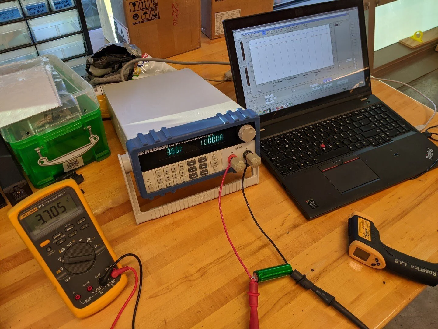
Using an electronic load, we perform discharge tests on our Sony VT6 cells. The cell is rated at 3000mAh with a continuous max discharge of 30A (temperature limited). We will be limiting the discharge to 10A per cell which will yield a max discharge for the pack of 200A.

Here we are seeing about 2750mAh down to 2.8V during a 10A discharge. We don't plan to discharge the cells beyond 3.0V when installed in the aircraft. The 3000mAh rating is for a 200mA discharge down to 2.0V.

CAD rendering of the 1S20P module. Cells are held in place with standard 18650 battery holders and custom 3D printed ends. Parallel connection are made via spot-welded nickel strips and copper bus bars.

CAD rendering shows the overall layout of the pack. The assembly includes cooling fans, main connector, main disconect, contactor, fuse, and DC/DC converter.

Another view from the top. The enclosure will be welded aluminum. Cover design is TBD.

The cells arrived bare (no insulating washers or heat shrink wrap). After we measured the voltage of all cells to make sure we had no duds, we began to install the insulators and heat shrink.

Assembly line in place to prepare all 560 (acutually 600 including those used for testing) cells.
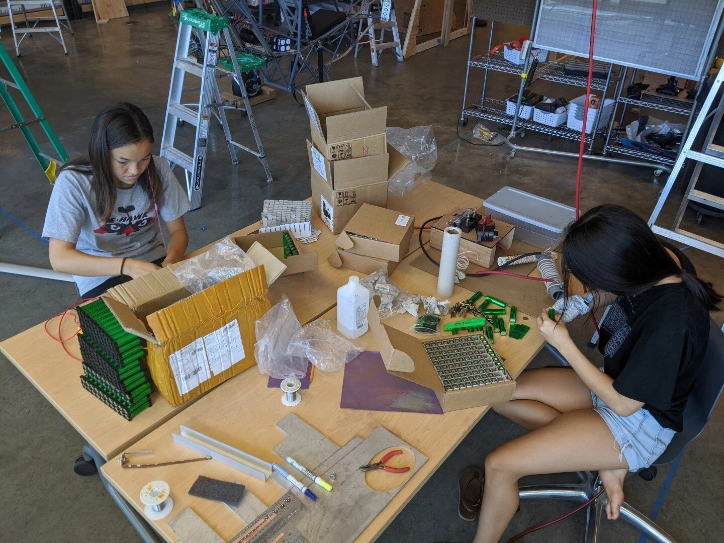
After the cells are wrapped, assembly of the modules begins. Cell holders are configured to arrange the cells in a 2 x 10 array.

Battery modules begin to stack up. We need to produce 28 of them for our 100V nominal pack.

Bus bars being cut from 1/8" copper sheet.

Brass hex nuts are soldered onto the terminal end of the bus bar.

Bus bars pressed into the custom 3D printed module tops.
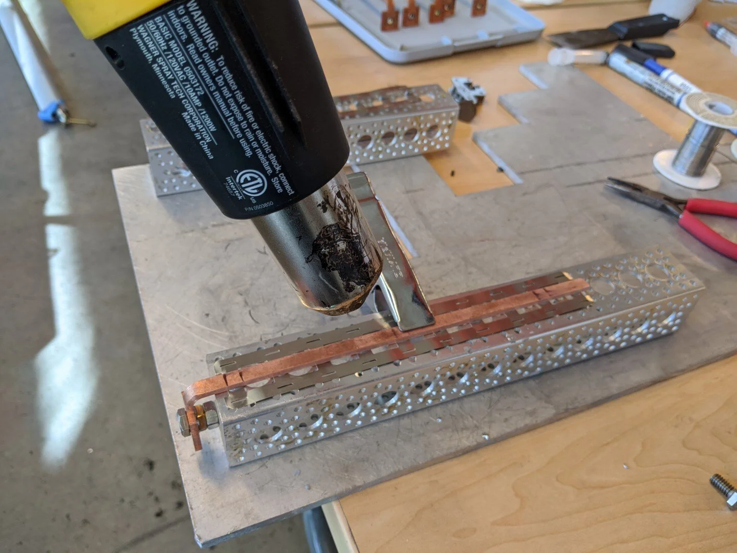
The nickel strip (0.2mm) is soldered to the the copper bus bar using heat gun and solder paste.

Completed bus bars receiving a cleaning bath in isopropyl alcohol to remove any flux residue. All bonding surfaces must be clean prior to spot welding.

Bus bars ready to be spot welded to the cells.
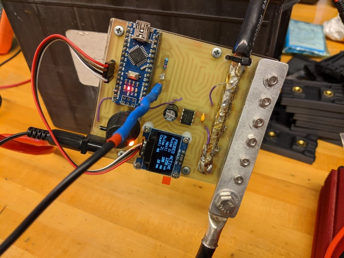
Here is our custom Arduino-driven spot welder. The pulse duration can be adjusted to optimize the weld. We used 2 deep cycle lead acid batteries as the power source.
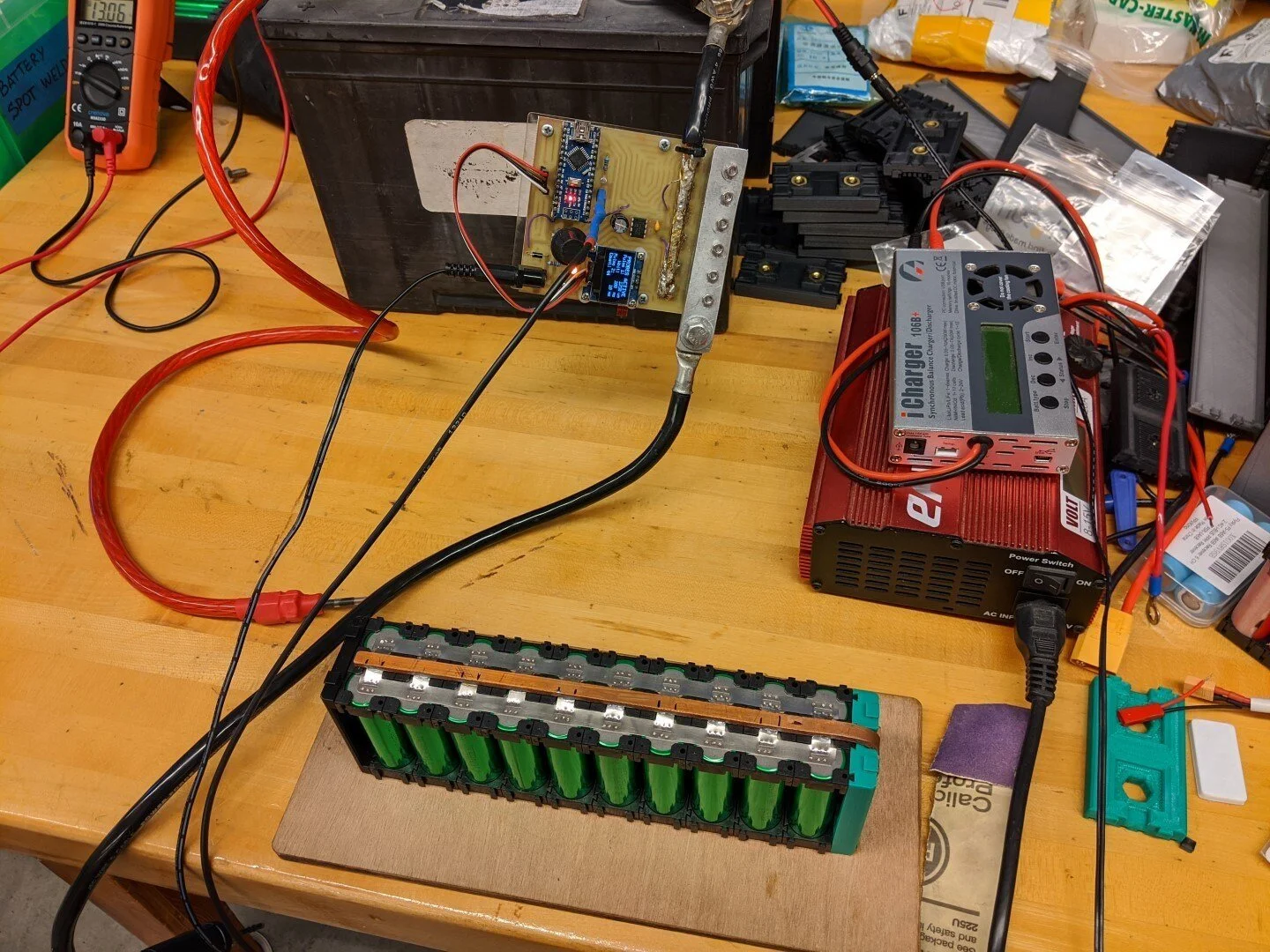
The negative side of this module has been spot welded. We perform 3 welds per battery terminal, both on the positive and negative ends. That's 3,360 welds for the entire pack.
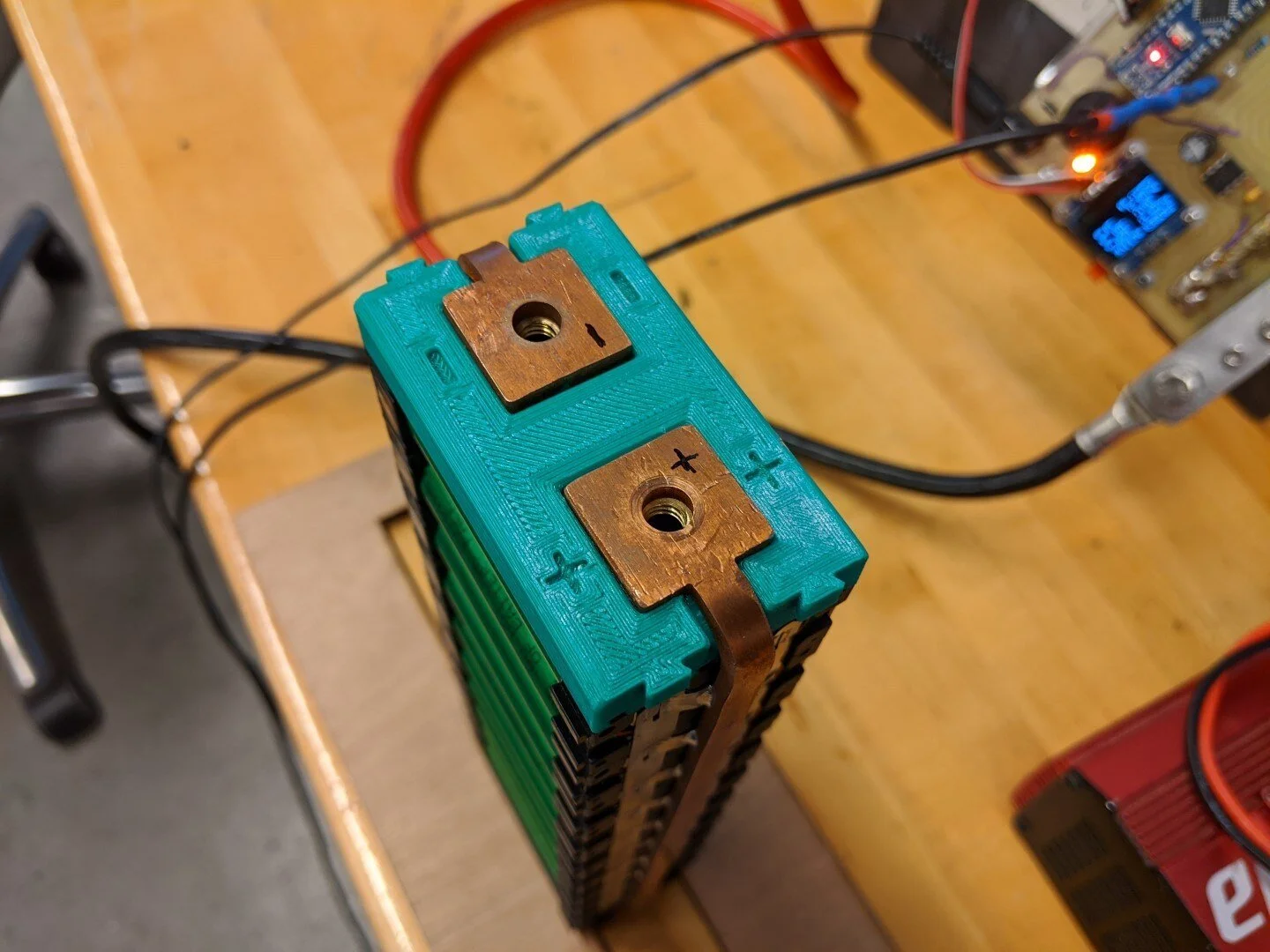
A completed battery module without the insulating side covers installed.
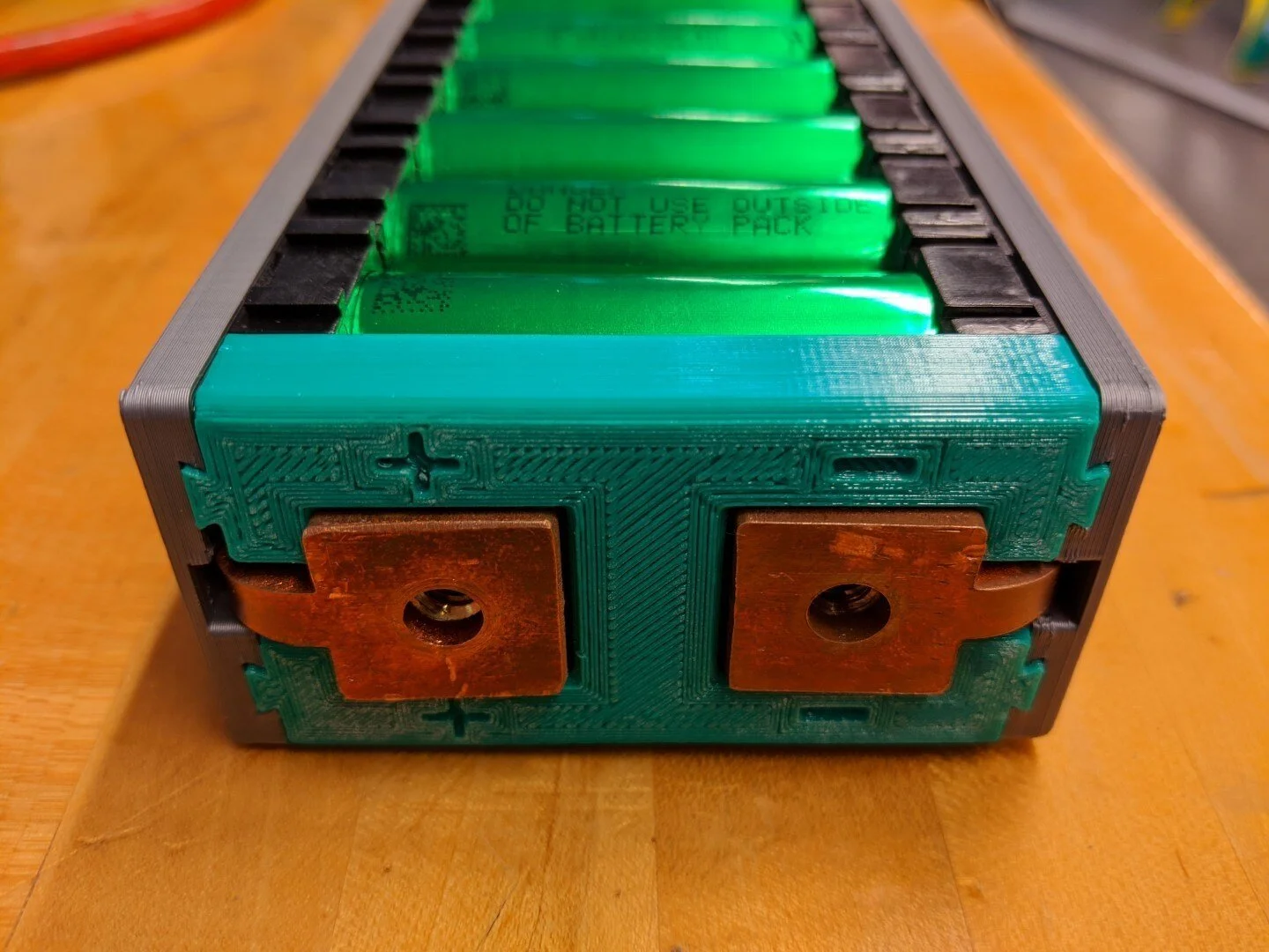
Side covers installed.
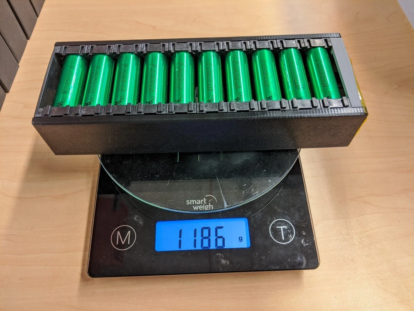
The all-up module weight of 1186g translates into a pack energy density of roughly 168Wh/kg (based on useable energy at 10A discharge). This will decrease some when we add in the weight of the enclosure.
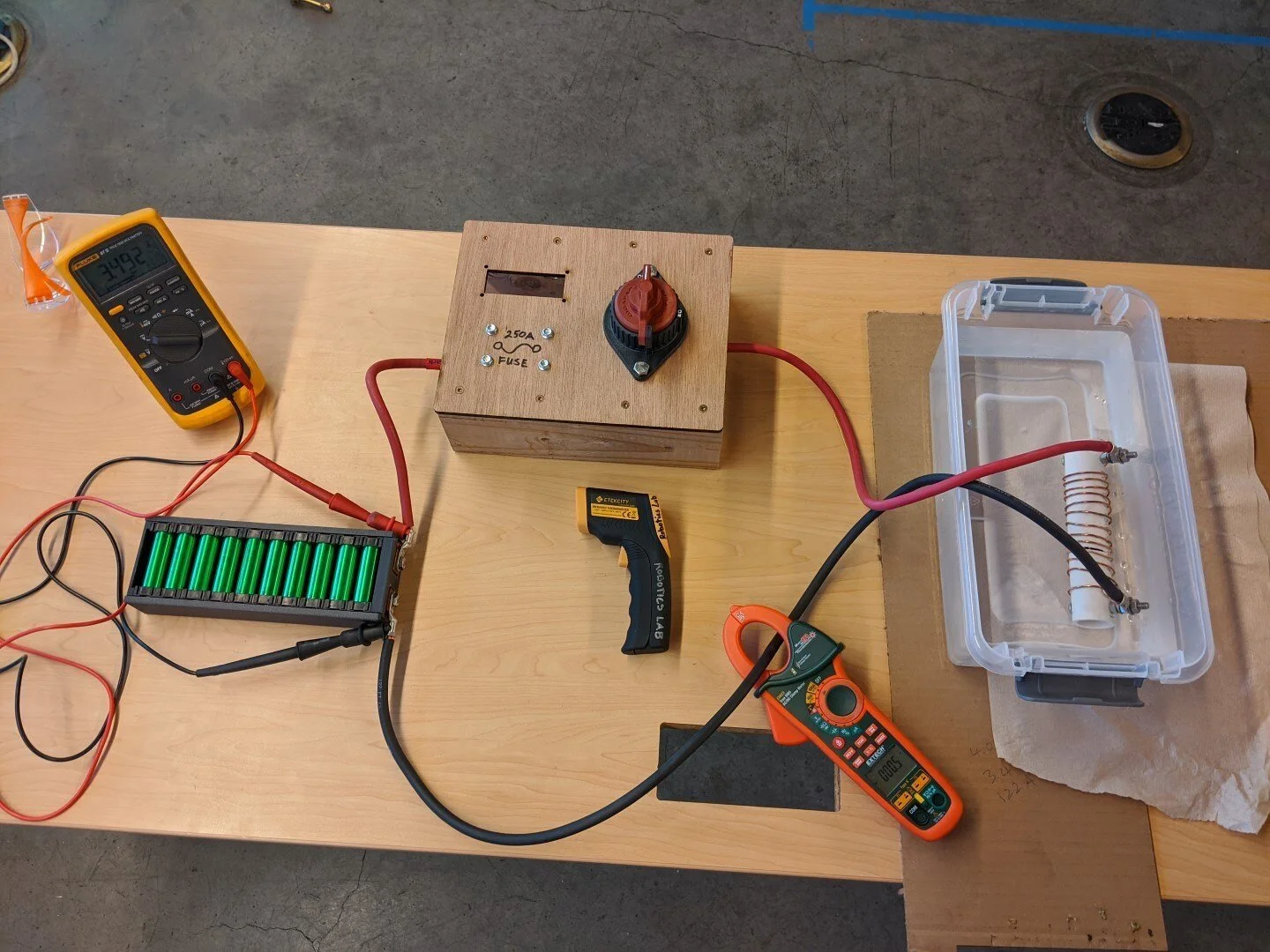
Prior to assembling all 28 of the modules, we did a high current discharge on a test module to make sure it held up. The test setup consists of the battery module connected to a custom made power resistor through a fuse and main disconnect switch. The resistor was submersed in ice water so as to keep its resistance constant for the duration of the test. The resistor was sized to sink approximately 200A which is our anticipated max current draw. At 25C ambient temperature, a 6 minute, 200A discharge yielded a battery temp increase of 21°C and a bus bar temp increase of 11°C. The greatest increase in temperature was in the #4 wire as it increased by 31°C.
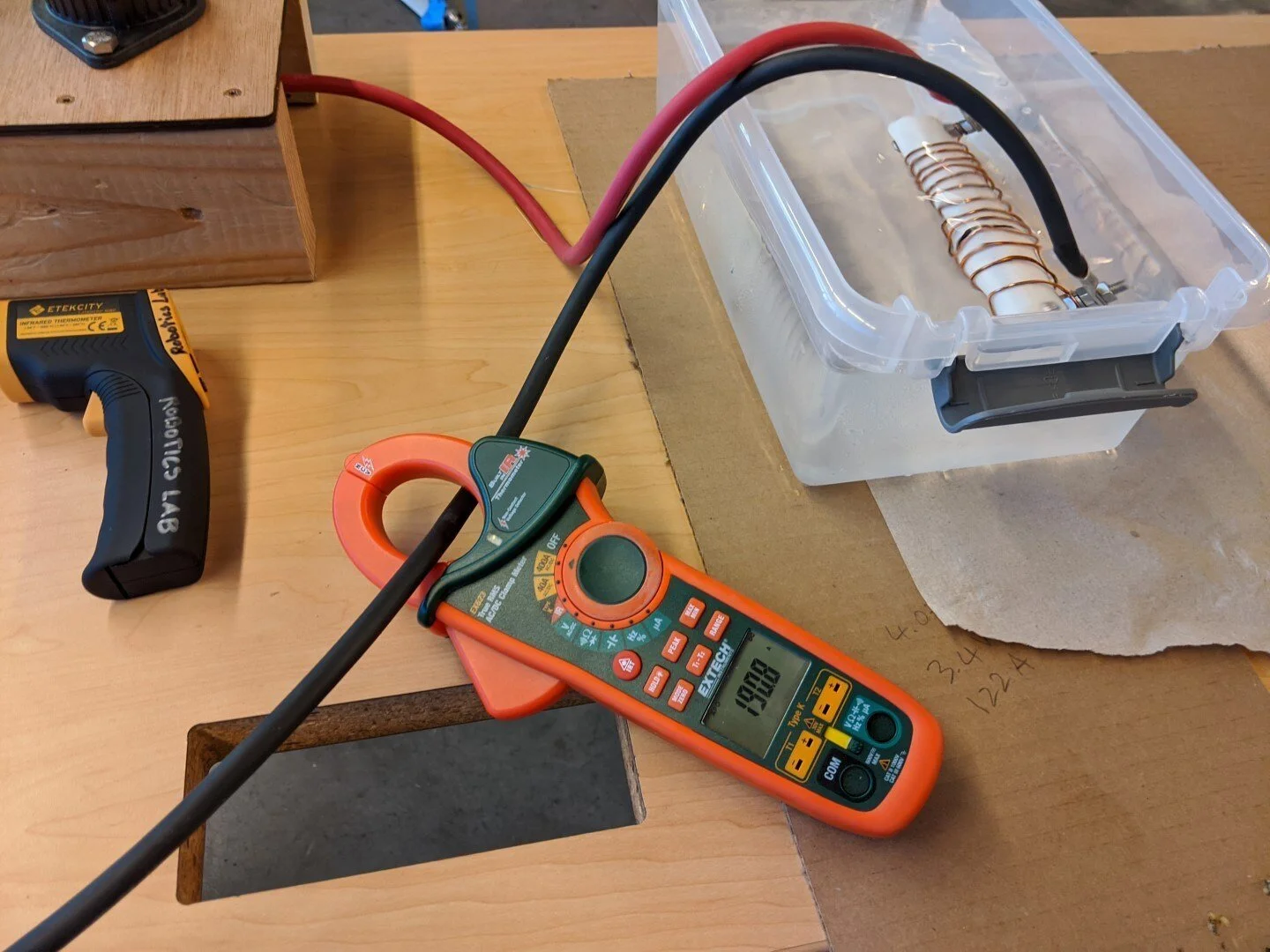
At 190A our 28S pack would be providing roughly 19KW of power.
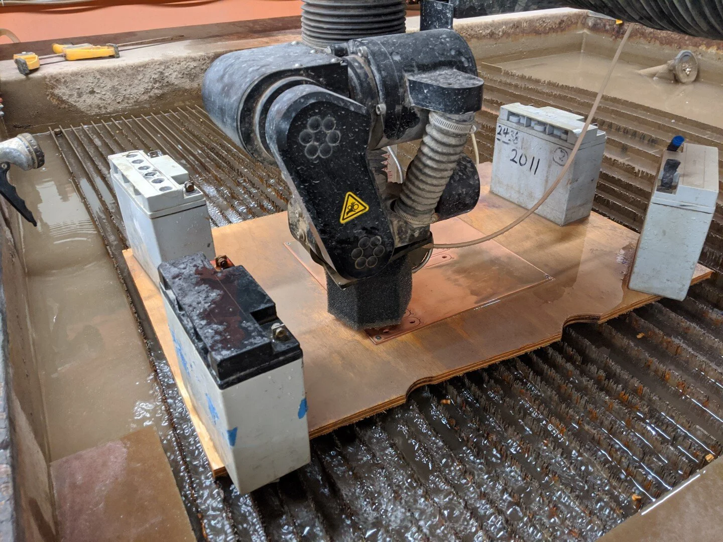
Using the waterjet to cut battery module connectors from copper plate.
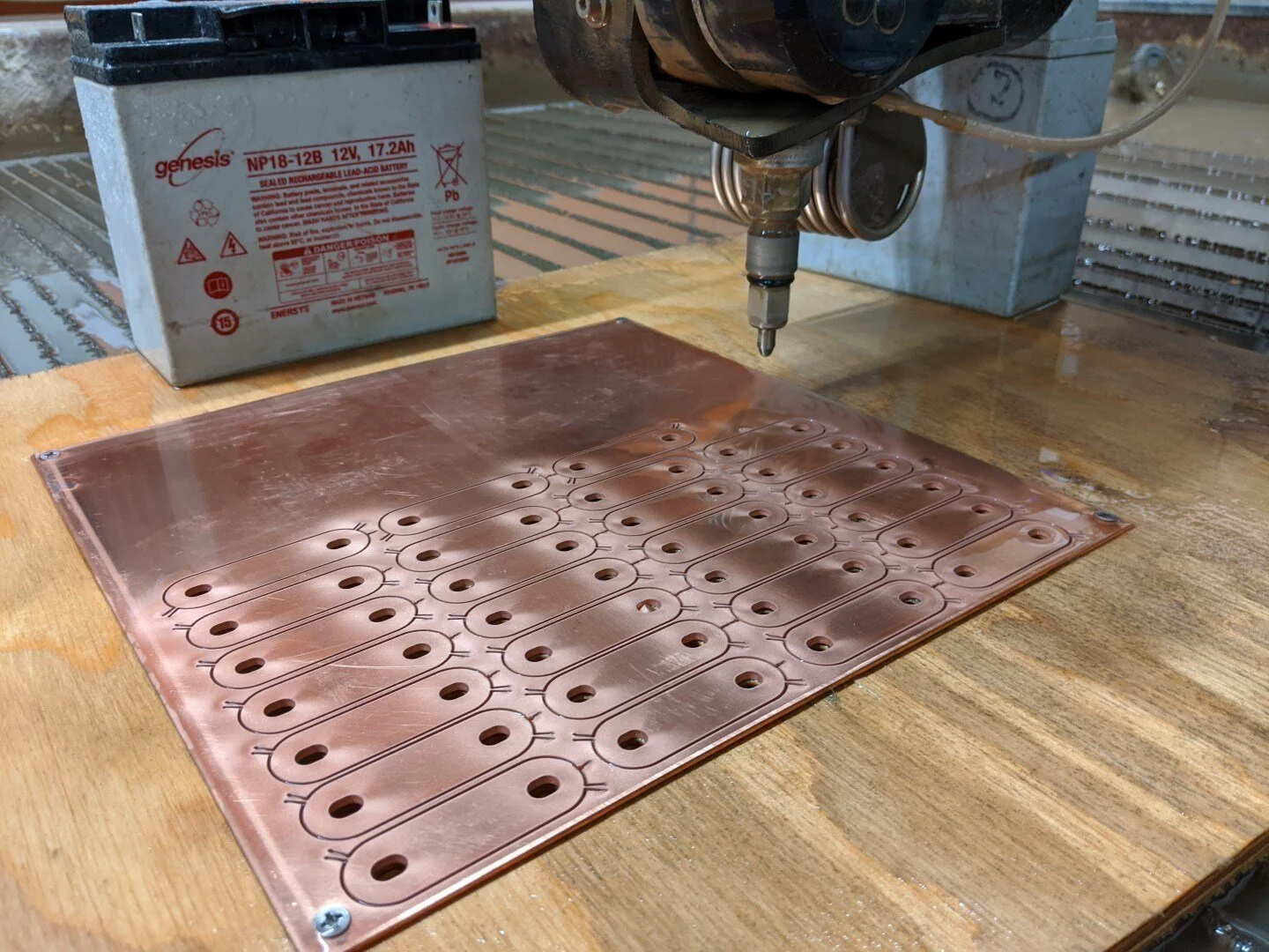
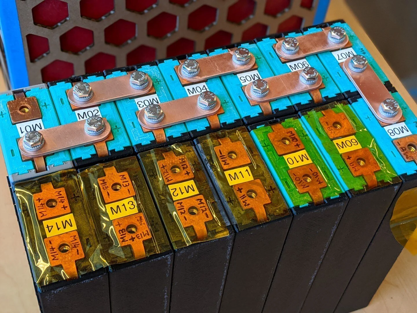
The modules are configured in series using copper terminal connectors secured with 1/4-20 fasteners and wedge lock washers (Nord-Locks). It's not obvious from the picture but each of the 7 modules in a row is mechanically interlocked with the adjacent module via the cell holders.
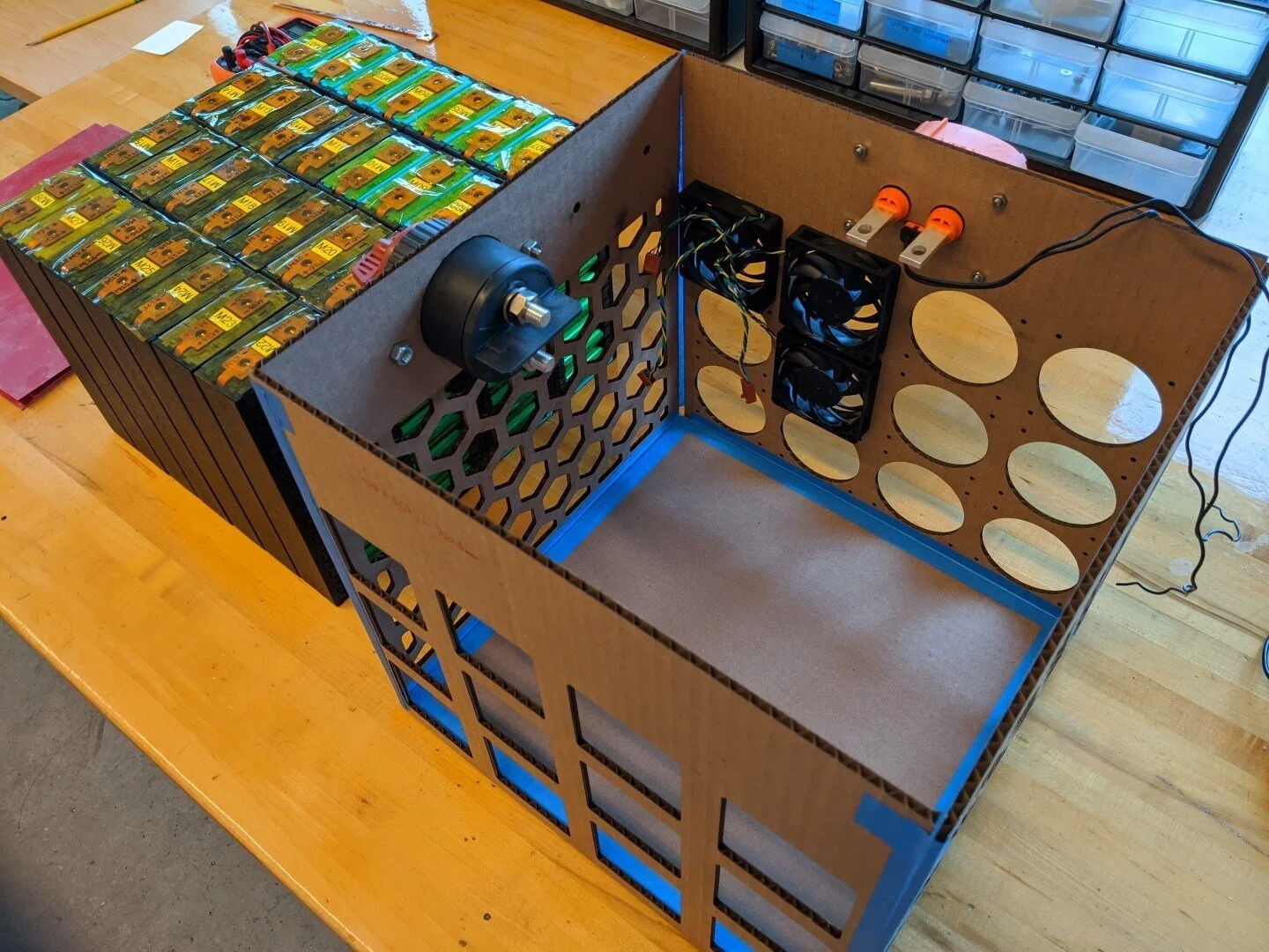
Cardboard prototype of the battery enclosure is evaluated prior to aluminum fabrication.
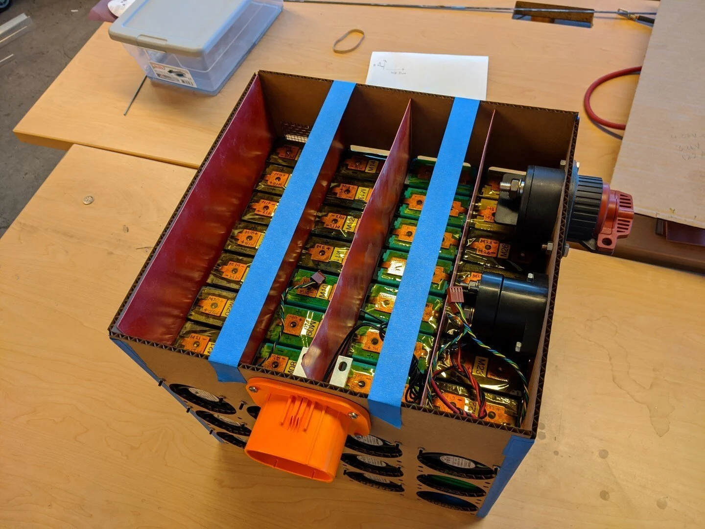
Modules installed in prototype enclosure with balance of electrical components. Each row of 7 modules will be separated with electrical grade fiberglass (GP03) sheet.

Aft (air exhaust) side of pack.

Cooling air intake side of enclosure.
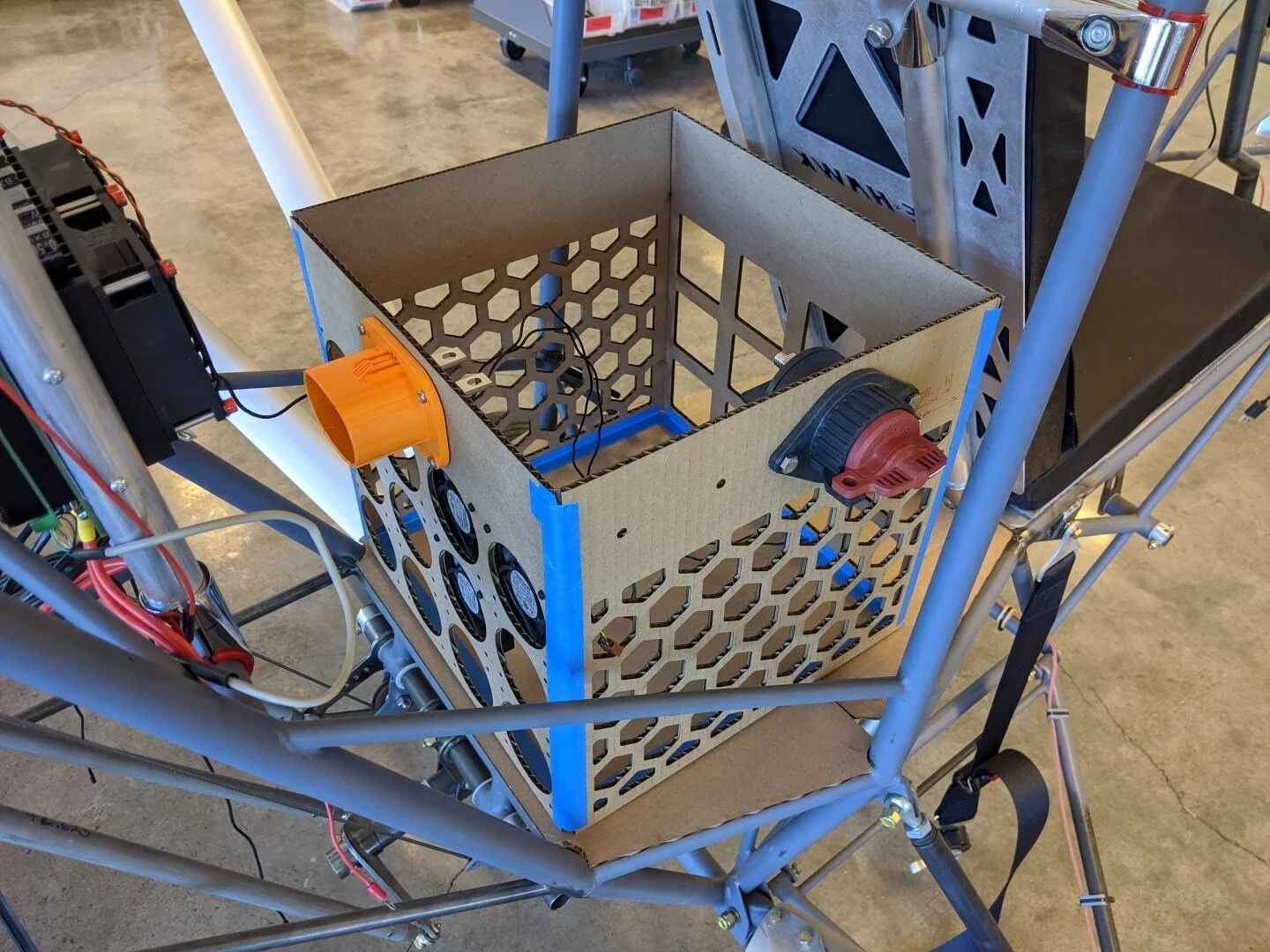
Battery pack fit check.
