Motor/Battery Instrumentation Display
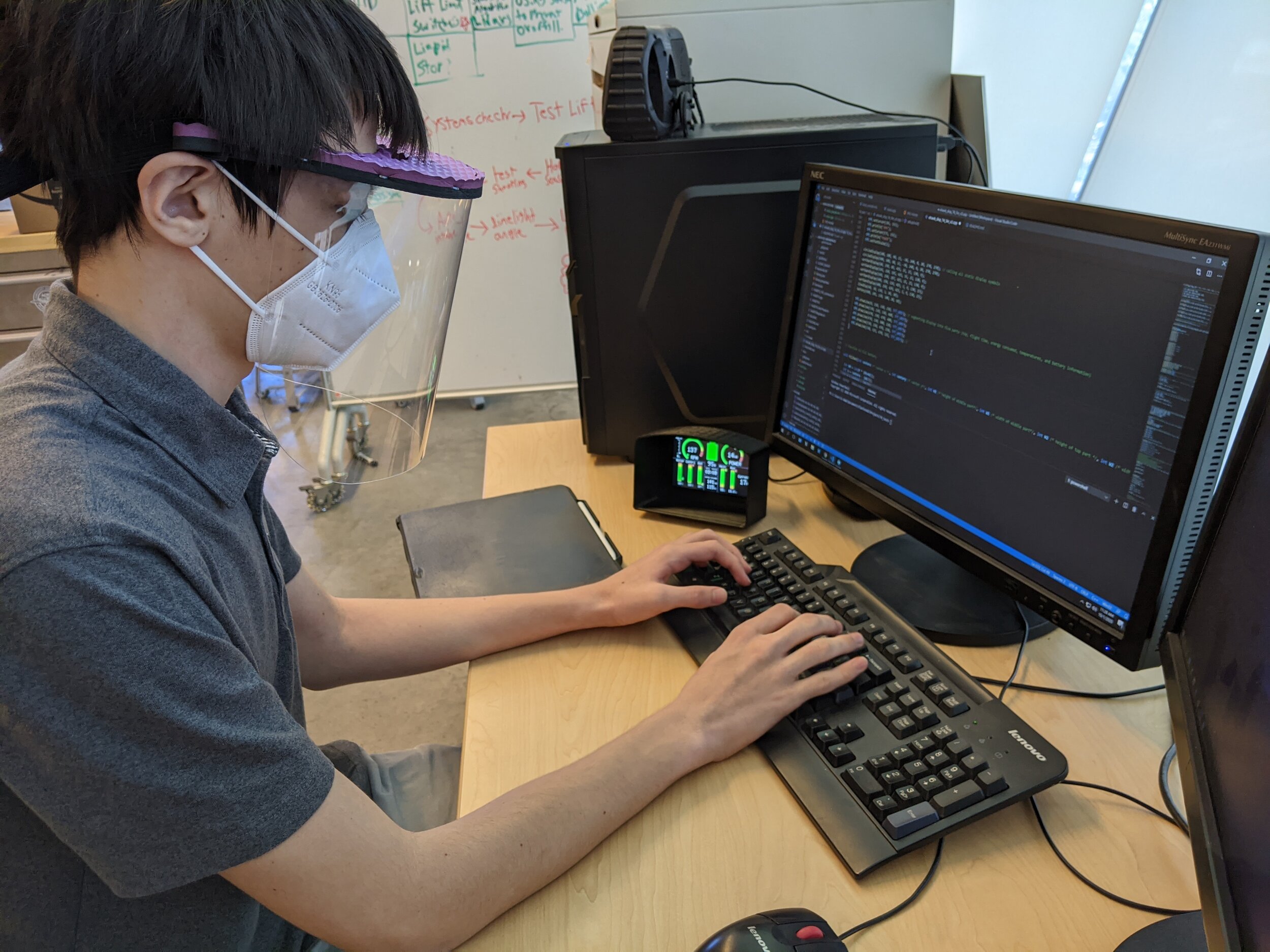
Critical information from the motor controller and avionics must be displayed on some sort of onboard device. Over the past two months, our team has discussed, designed, and implemented a general display layout. Our overall instrument panel will consist of some switches and circuit breakers, two small TFT displays for flight instrumentation, and a larger TFT display (5” 800x480, RA8875 controller, 4-Wire Serial SPI) for motor/battery system information. In the next few weeks we will be working with the CAN bus to receive, interpret, and display necessary motor/battery system information on our chosen layout. Before working on the display, we made the choice to program using the Teensy 4.1 development board because of its high speed, CAN bus support, microSD slot, and interfacing capabilities with Arduino (Teensyduino). We will likely use multiple microcontrollers in our avionics system to work through single point failures.
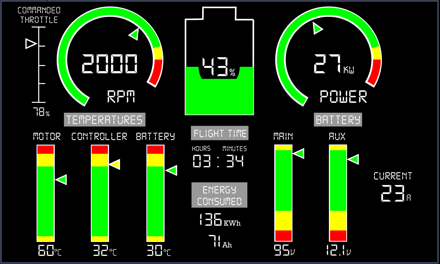
The process began, as it always should, with research. We looked at a variety of existing aircraft displays and came up with a list of readings to be displayed with desired prominence/size. Each reading would take the form of a bar, line, dial, or numerical readout, so we began programming functions to represent such elements on small 2.8” TFT displays. Each member of our team came up with a different display layout idea in Adobe Illustrator, and we each initially had two iterations of layouts. After receiving feedback from the rest of the group, we created a final layout drawing and started programming the designed layout that can output test data on a larger display. Adjustments were made along the way, such as segmenting the display with grey lines and increasing dial sizes to improve readability. We learned how to use PlatformIO for code development instead of using the standard Arduino IDE. The PlatformIO IDE will allow us to develop our firmware in a more professional manner.
By far the most challenging obstacle to programming the variable display was reducing flicker, which occurs on a TFT whenever a region rapidly changes from color A to B and back to A. The final code mitigates flicker by blackening readout digits and green segments of the battery only when necessary. Sunlight readability may pose a problem, so a shroud was printed. We have yet to test the display in higher levels of light exposure and may need to adjust color contrast to account for this. We may also change the text to seven-segment font, for aesthetic purposes and some of the battery read outs to be text-only. The video below shows the functioning display with simulated inputs. The next step in the process will be to read the actual data from the motor controller via the CAN bus to drive the display.