Progress Up To Summer Break
As the E-Hawk team prepares for exams during the final week of school leading up to the summer break we have quite a bit of progress to share. Our last fuselage frame update included the fabrication of the forward and aft bulkhead sub-assemblies, the landing gear box sub-assembly, the instrument panel sub-assembly, and the pilot seat sub-assembly. Since then we have welded together roughly 70% of the fuselage frame. We have also fabricated more of the flight control linkage hardware including control arms and bellcranks.
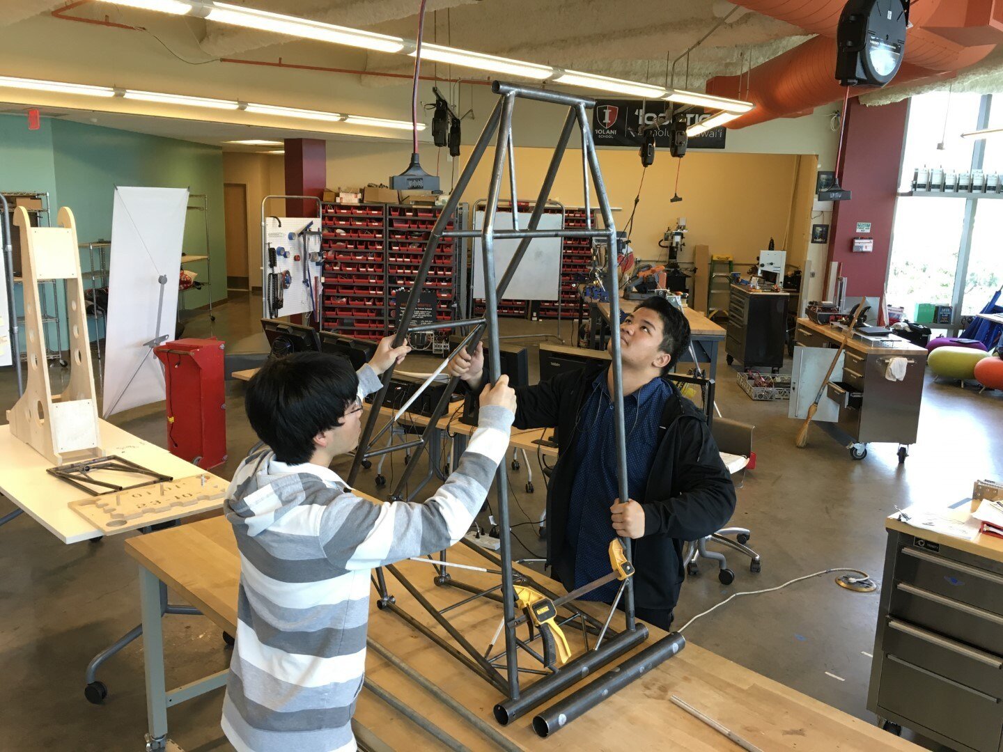
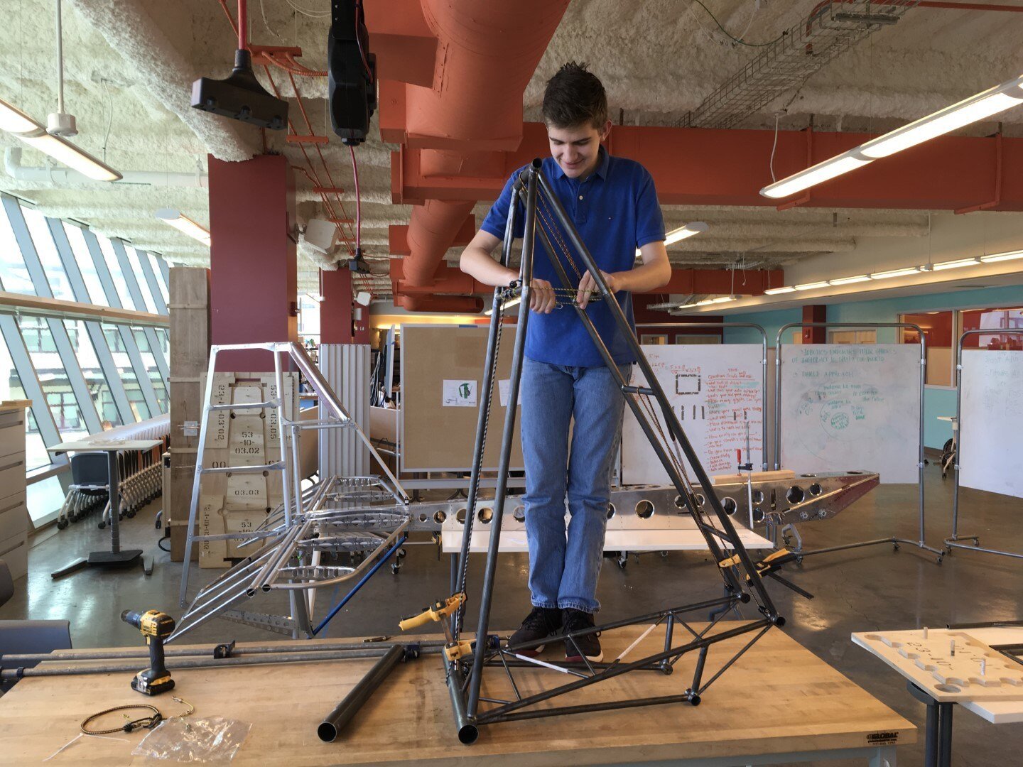
Once the tubes were properly fitted it was time to hold the sub-assemblies together using clamps and bungee cords.

This is the first time that the 3 main sub-assemblies (wing box and forward and aft bulkheads) are test fitted together. The initial fit was good and only minimal tube grinding modifications were required prior to weld-up.
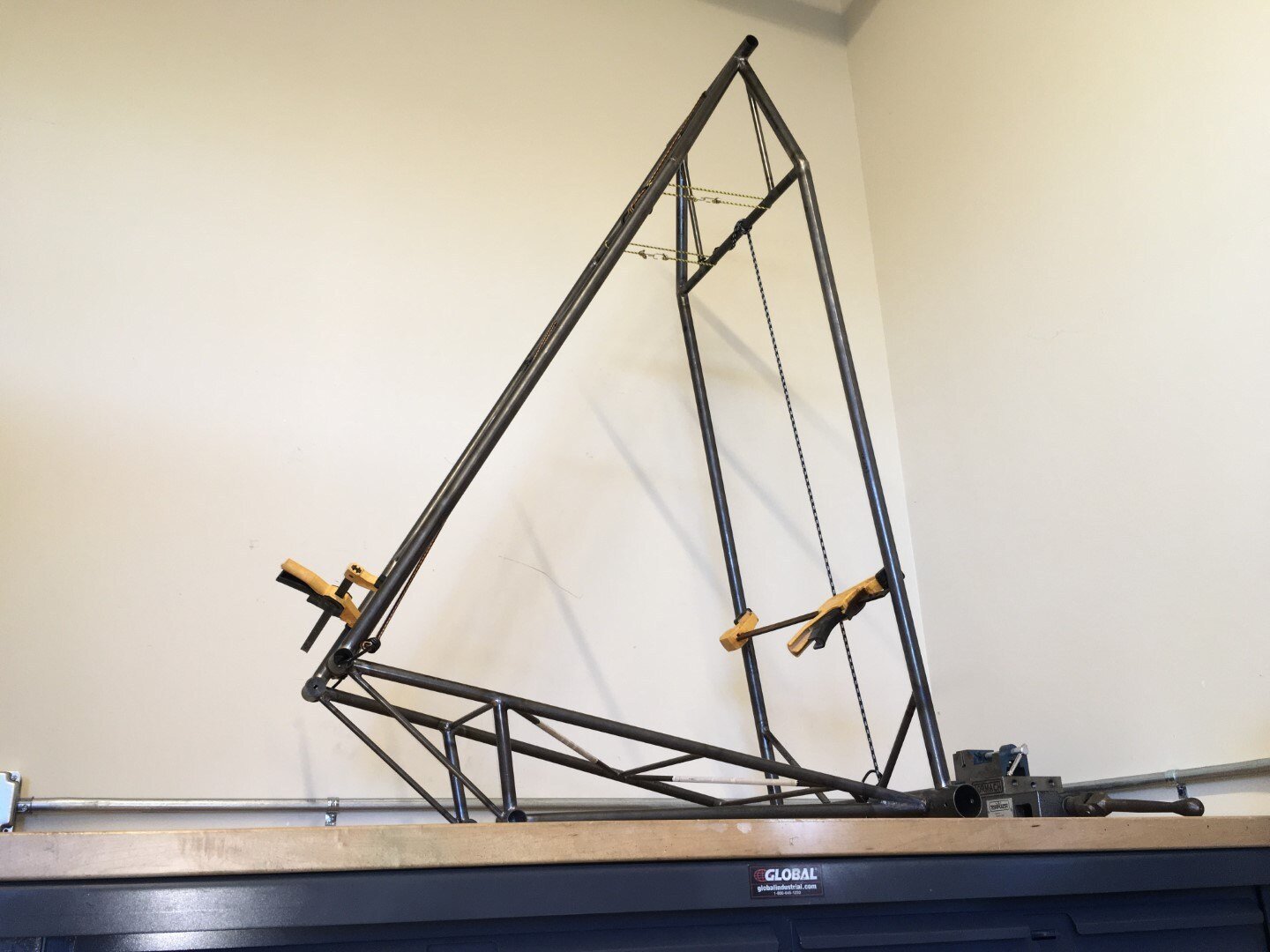
The triangular main structure moved into the welding station for tack-up.
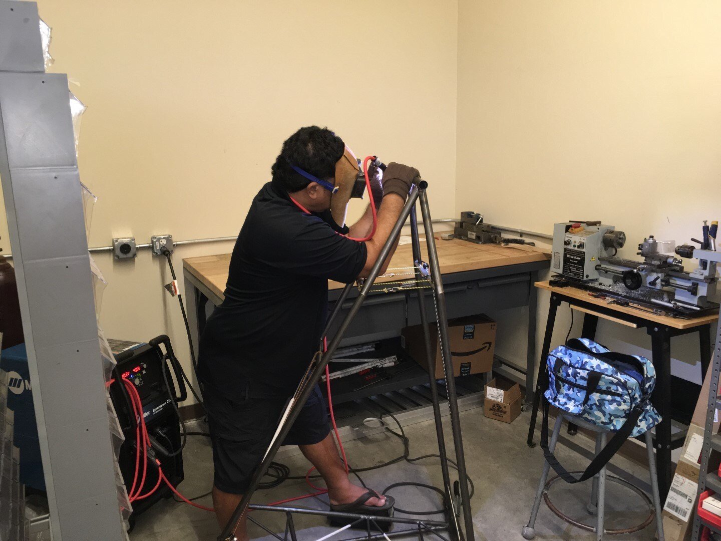
Our volunteer expert welder Terry helps the process along.
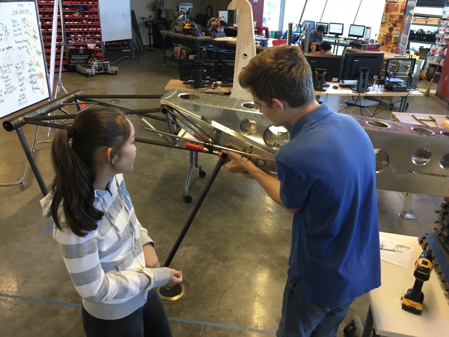
The main structure of the fuselage frame is fully welded here so an obligatory fit check with the tail boom was performed.
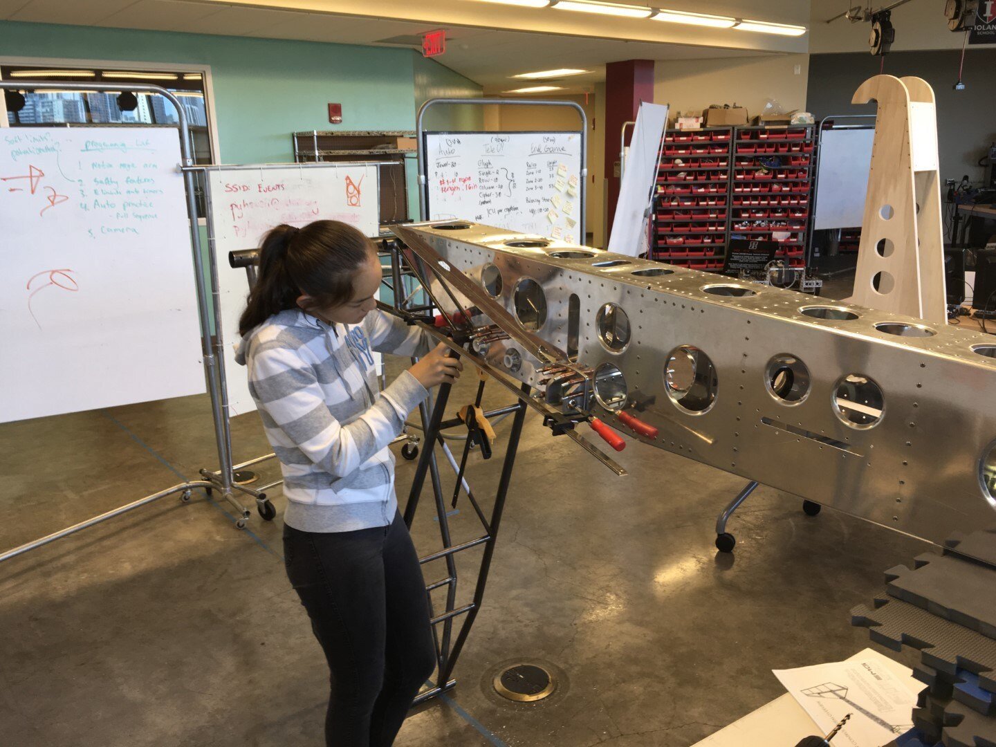
The wing box mounting holes align perfectly with the tail boom and 1/4" fasteners are temporarily inserted to hold the two parts together.
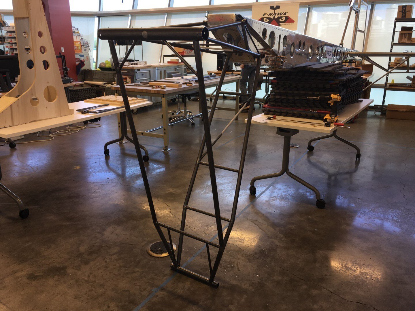
It's looking more and more like an airplane. Once we get the keel on the fuselage frame we will be dealing with the full length of the aircraft. At that point we will make another attempt to move the structure out of the building. If it fits down the stairwell we won't have to find a new location for final assembly.
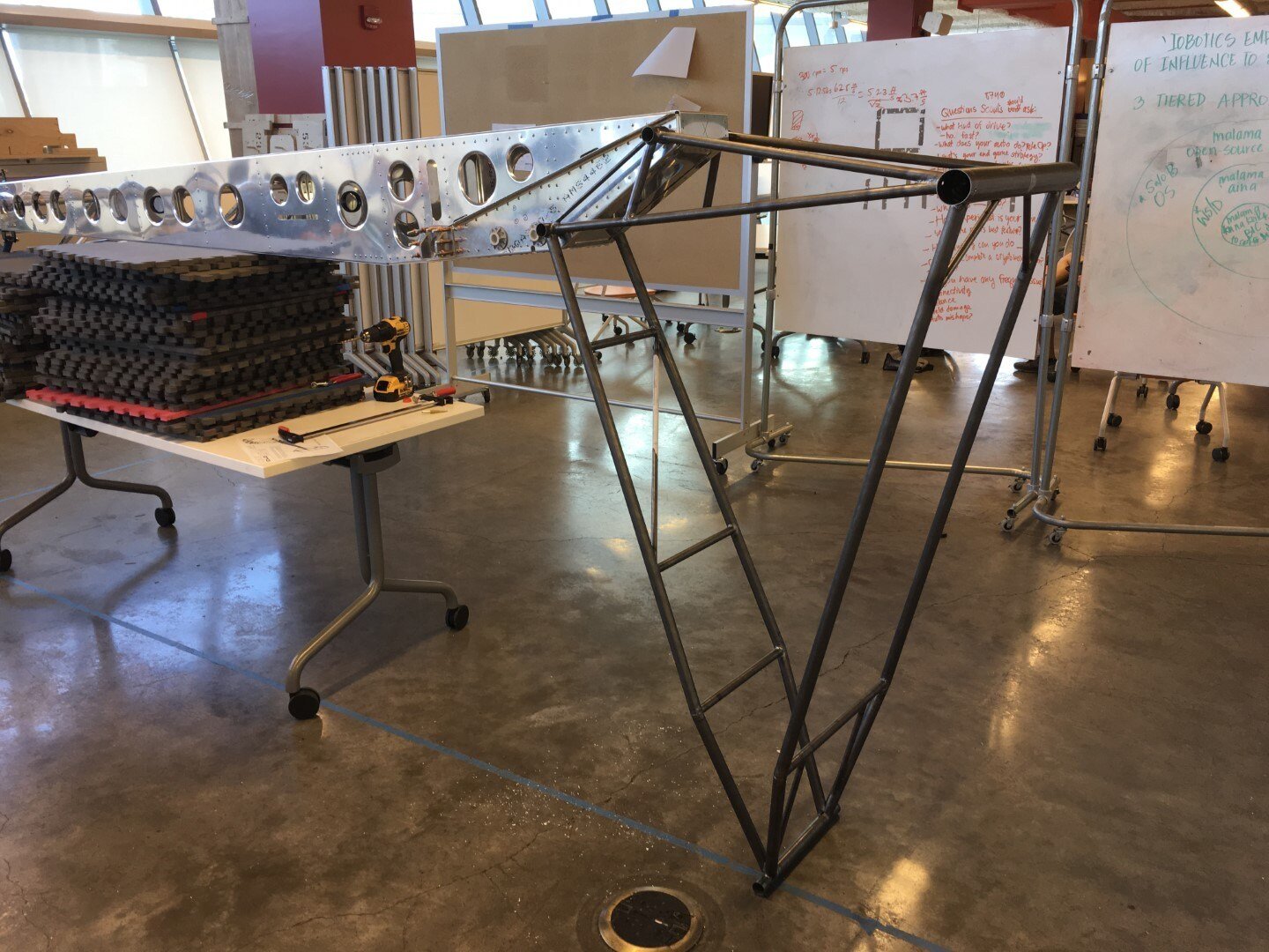
A view from the other side.
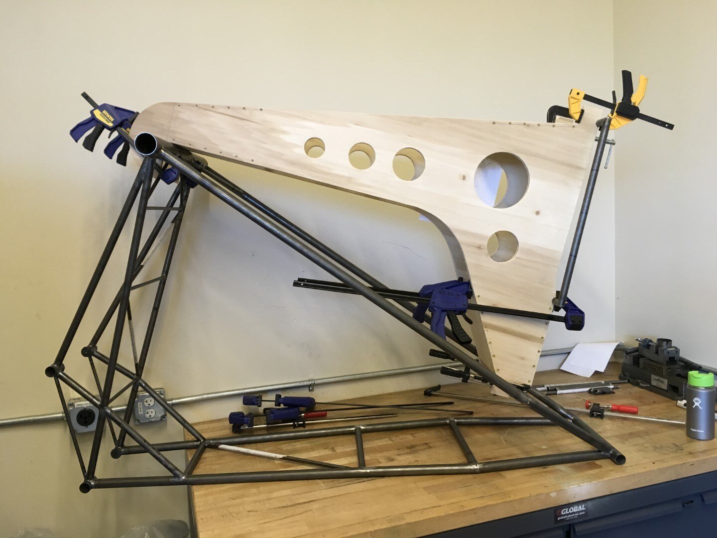
The fuselage frame moved to the welding station where the pilot seat will be tack welded into place.
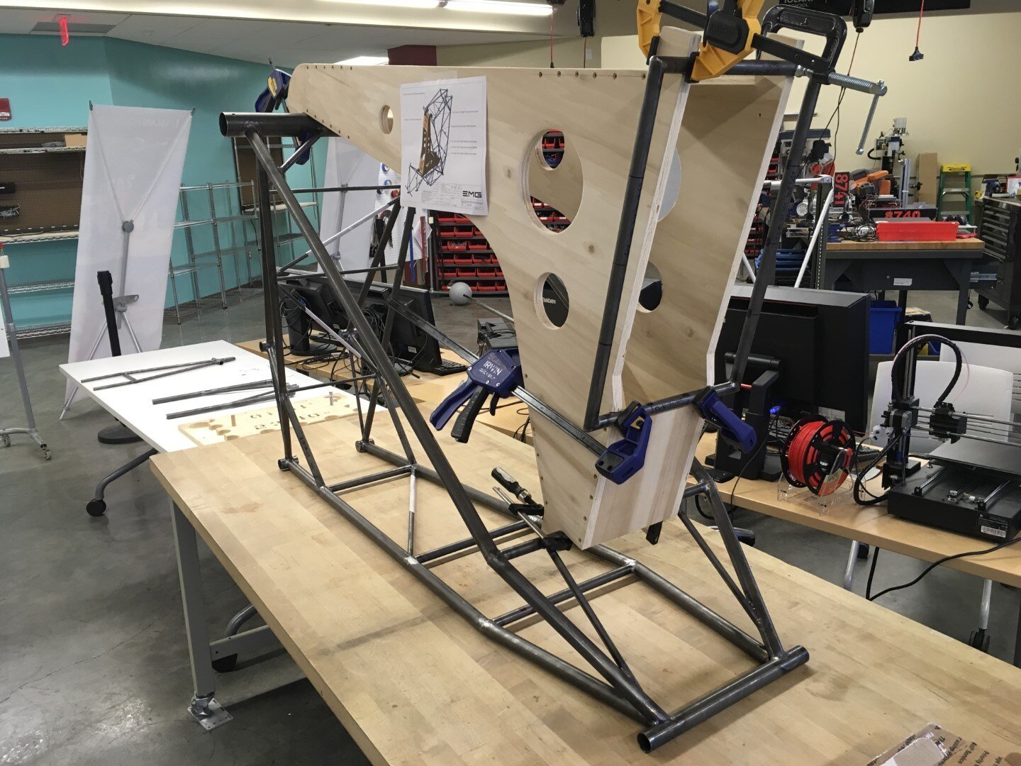
The pilot seat sub-assembly is held in place with the plywood tooling fixture. The jig locates the pilot seat precisely and holds it in place during welding.
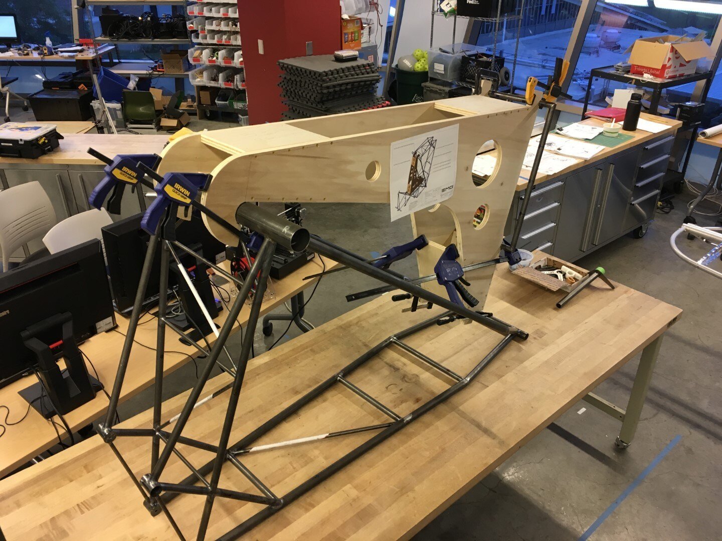
Clamps are used to secure all of the components.
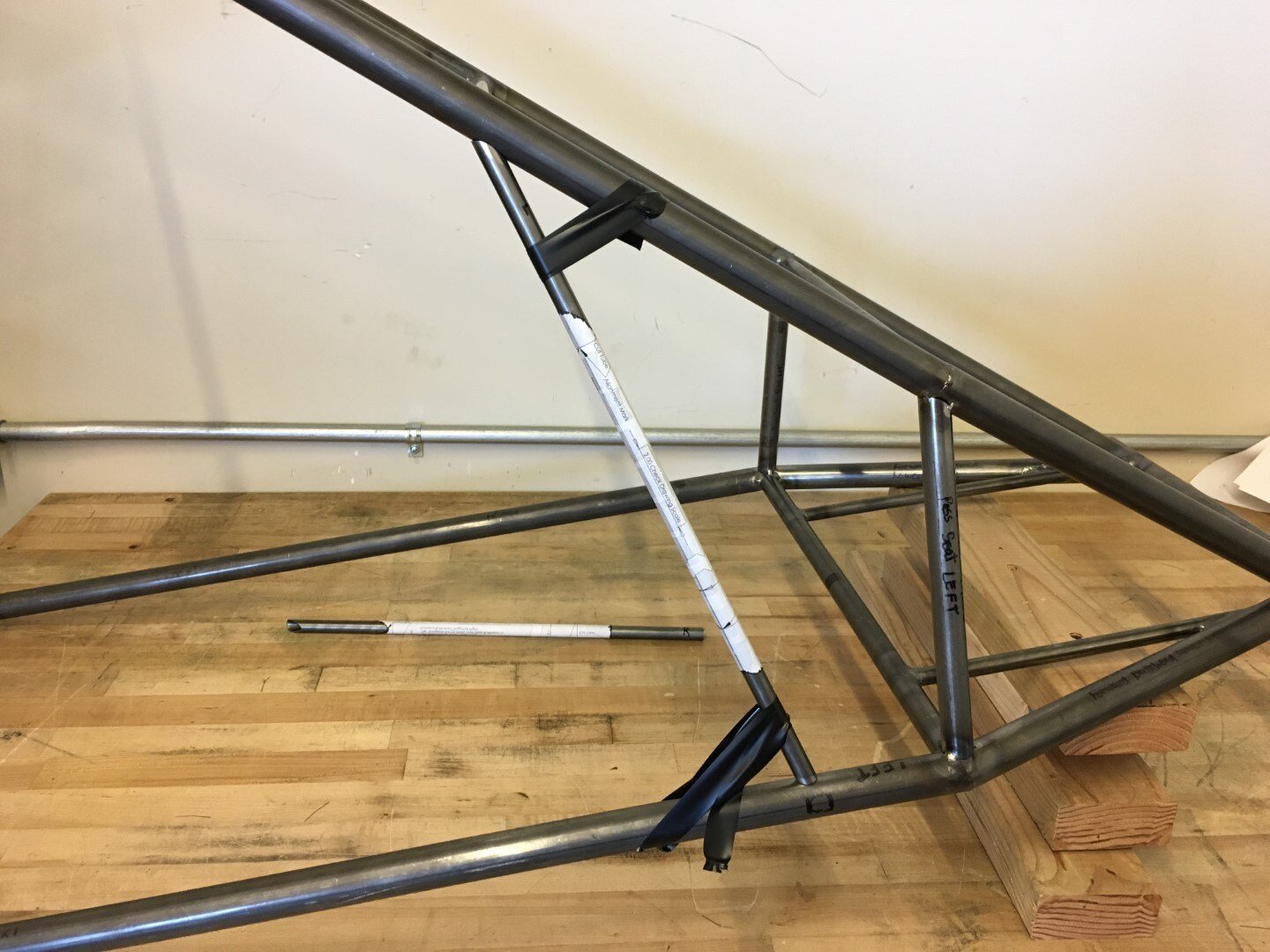
The left and right passenger seat tubes are tacked in place and the aft bulkhead to forward bulkhead diagonal is held in position with tape just prior to tack-up.
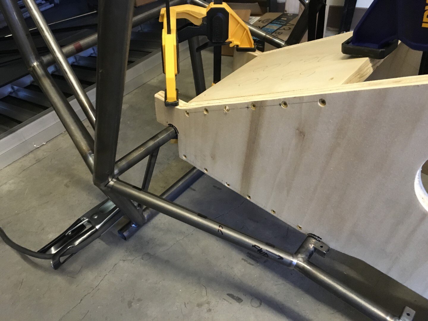
Note the seat tabs are already welded to the pilot seat sub-assembly.
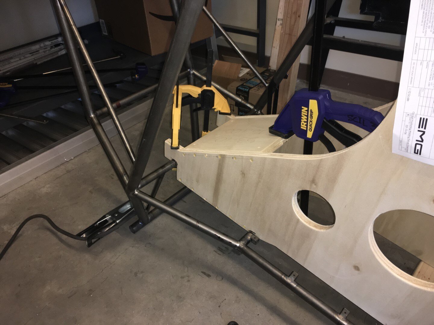
The Passenger Seat Transition Tube is shown here connecting the forward bulkhead to the aft end of the pilot seat.
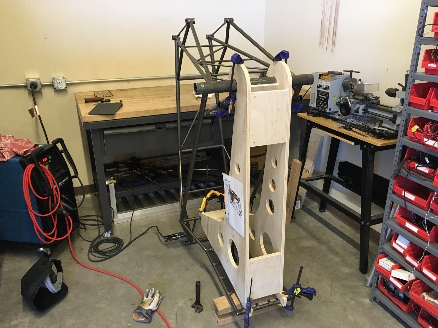
The pilot seat is now welded to the fuselage frame.
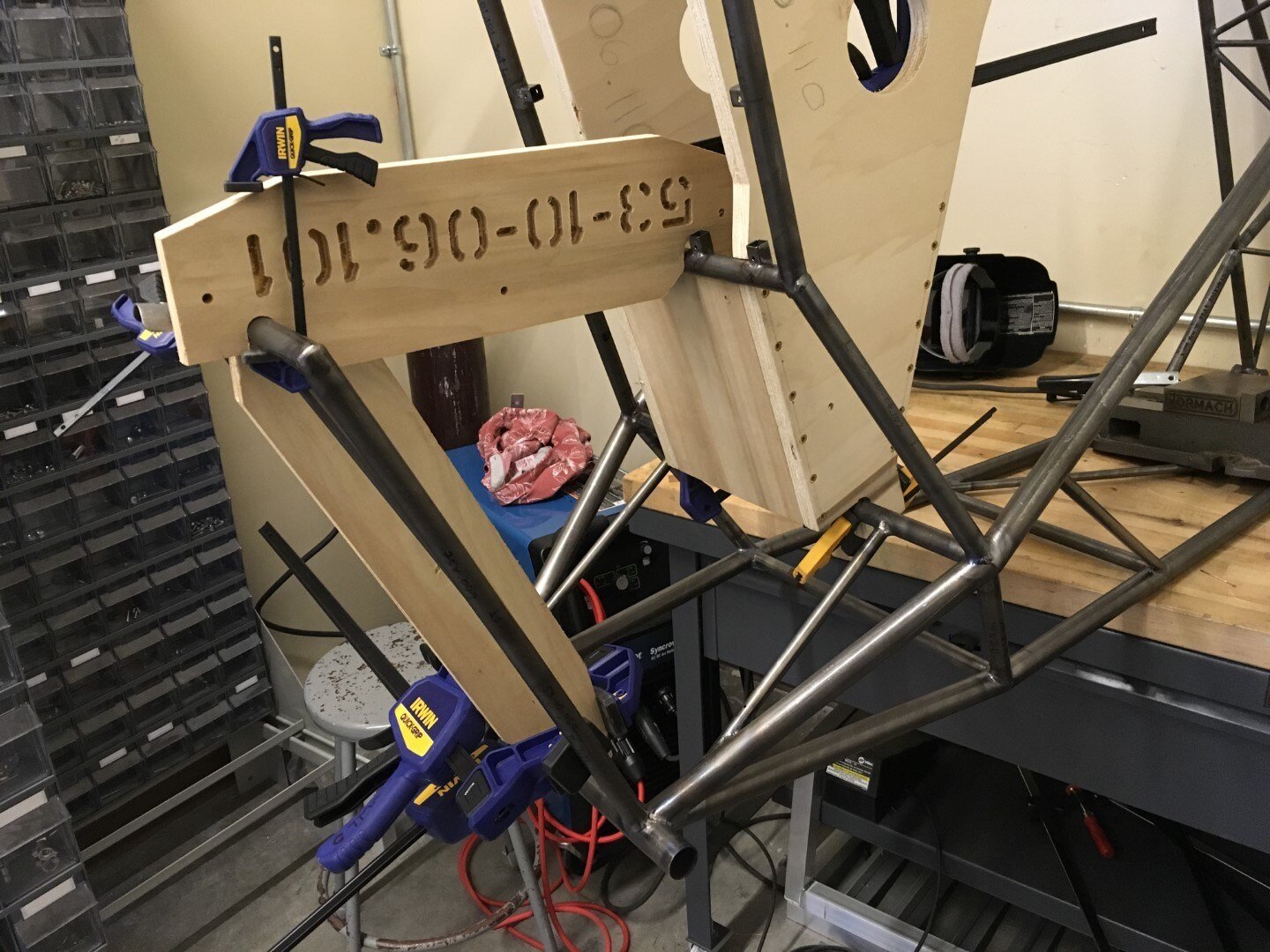
Another view of landing gear box sub-assembly in position.
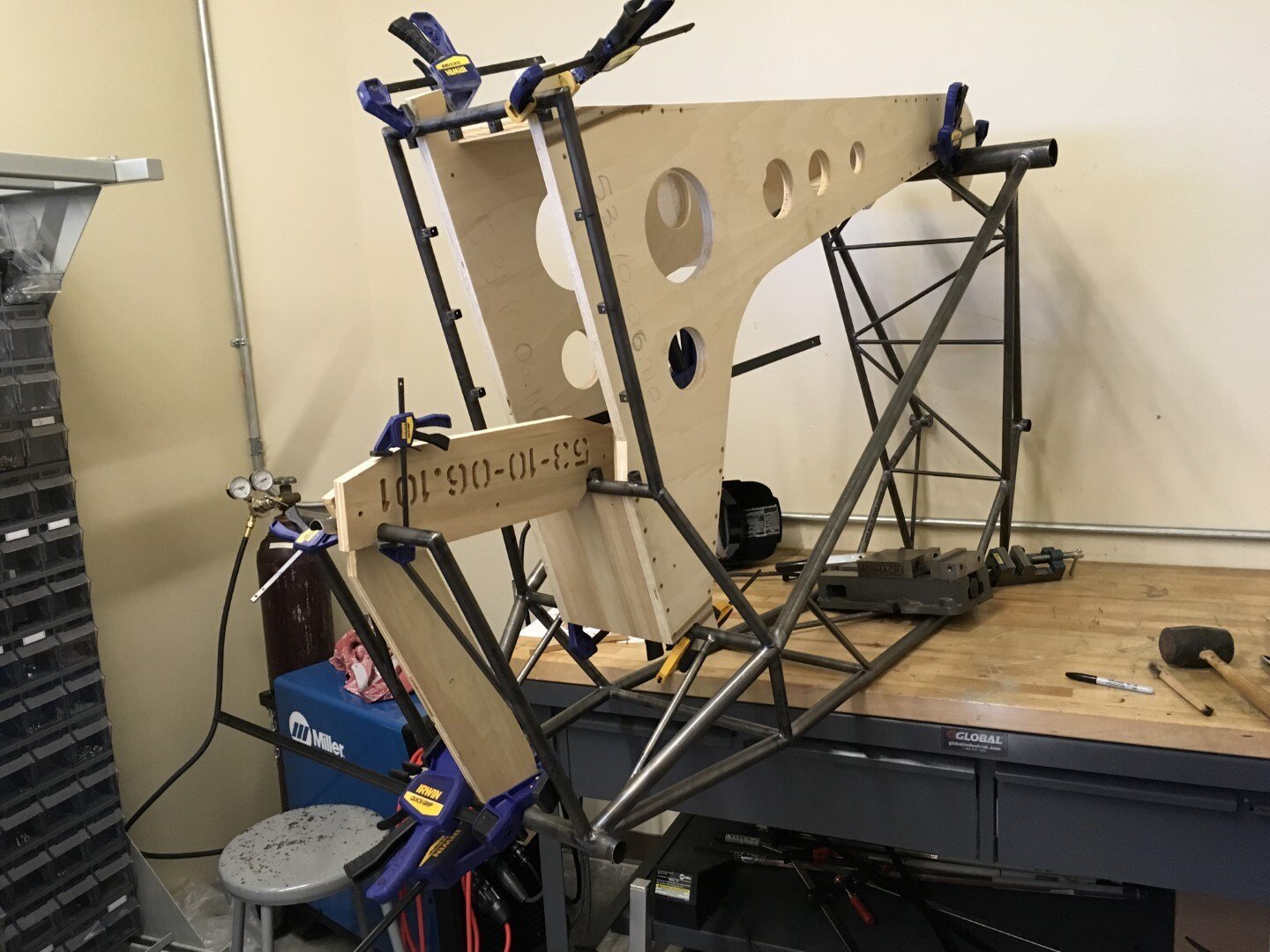
The next sub-assembly to be added is the landing gear box. More plywood tooling jigs are used for positioning.
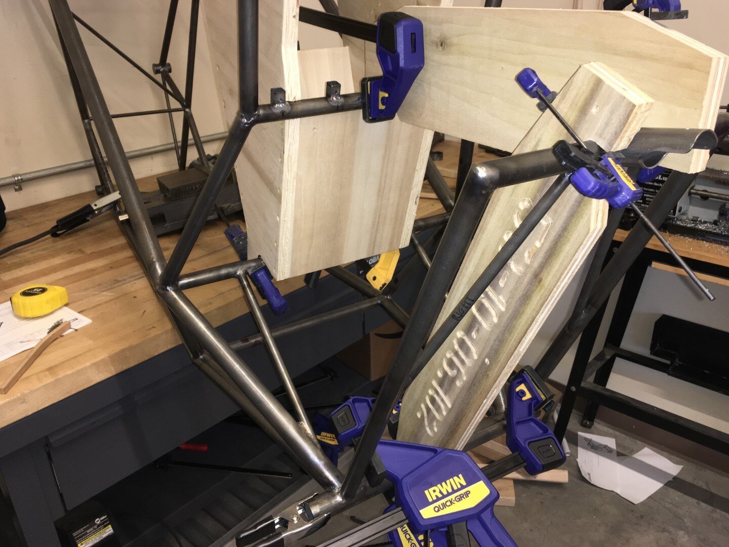
In addition to the welding fixtures, we measure distances left and right to make sure that everything is centered with respect to the fuselage frame.
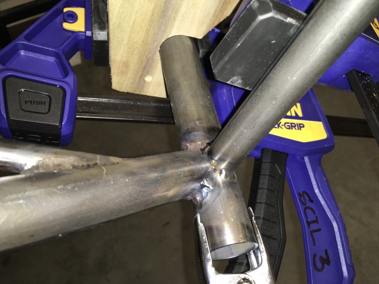
Closeup of the gear box tube partially welded in place.
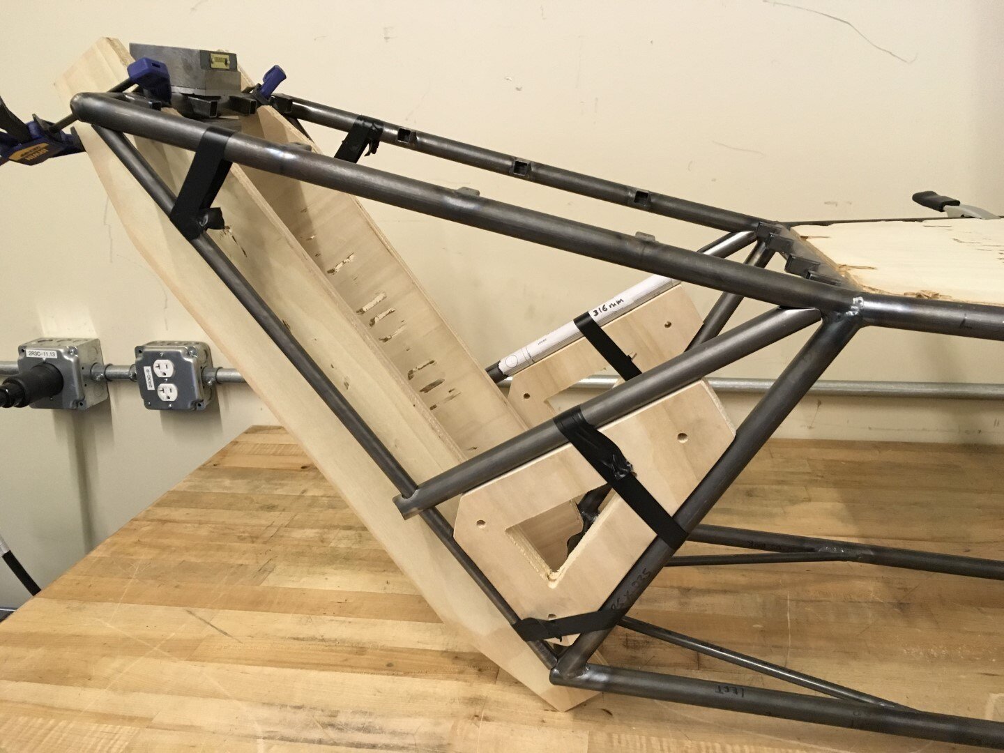
Here you can see that the Forward Seat to Gear Box tube has been welded in place. The two new parts are the Left and Right Forward Pilot Seat to Gear Box and the Left and Right Brake Mount tube which again are held in place using the tooling fixtures, clamps, and some tape.
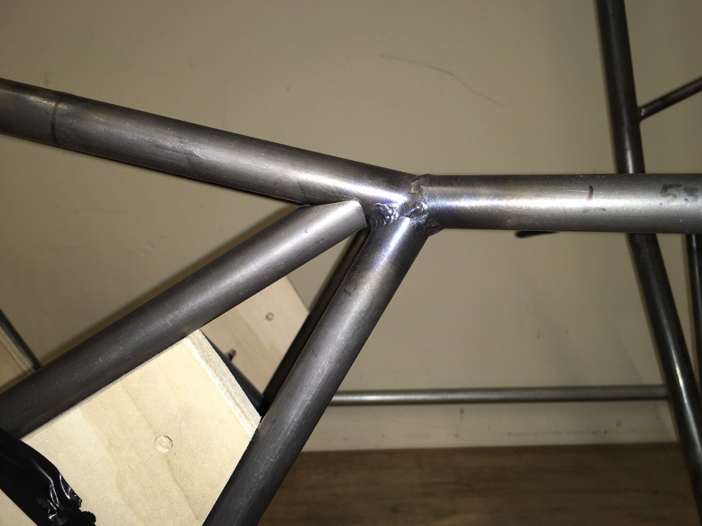
Closeup of tube fitment prior to welding.
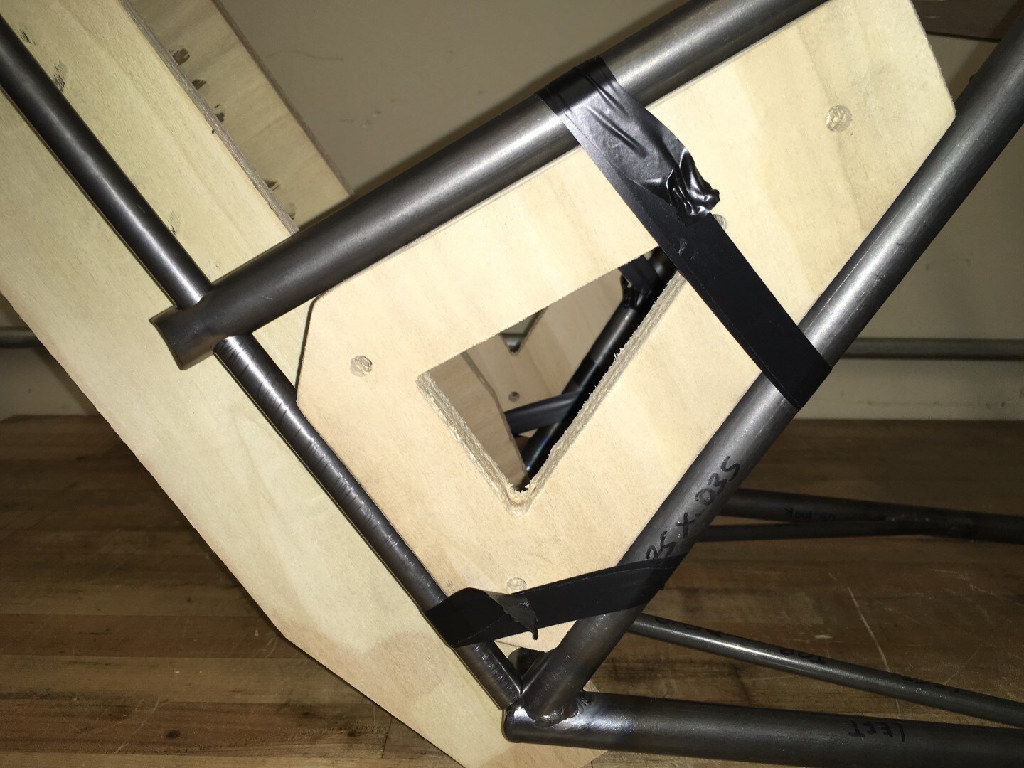
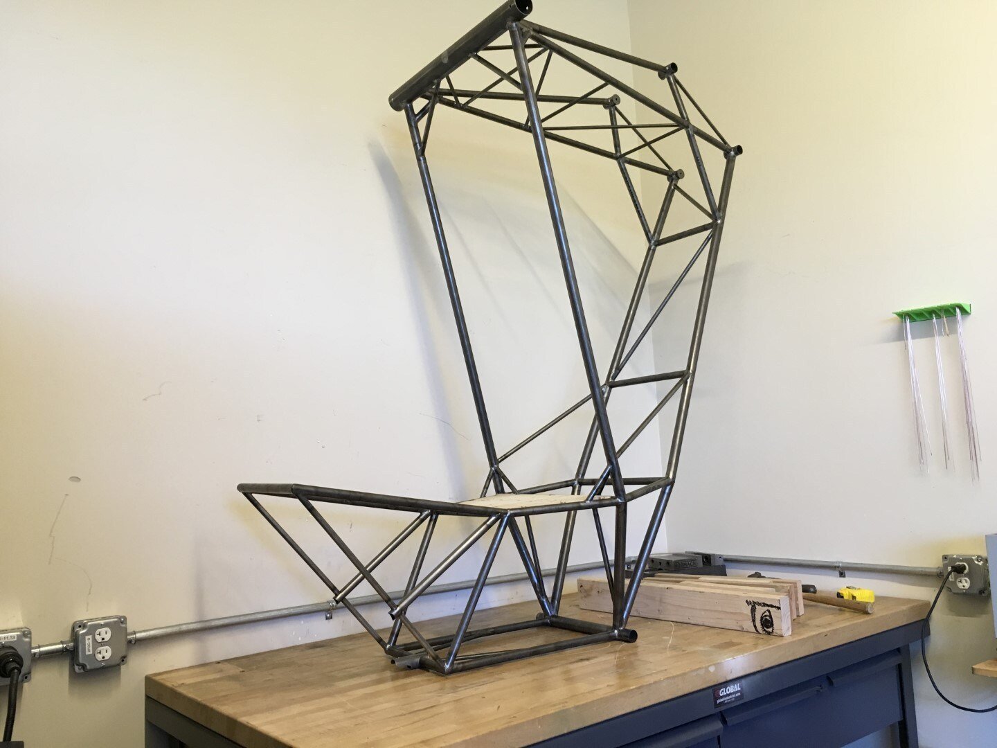
The Landing Gear Box and Pilot Seat are now permanently installed. The fame now stands on its own.

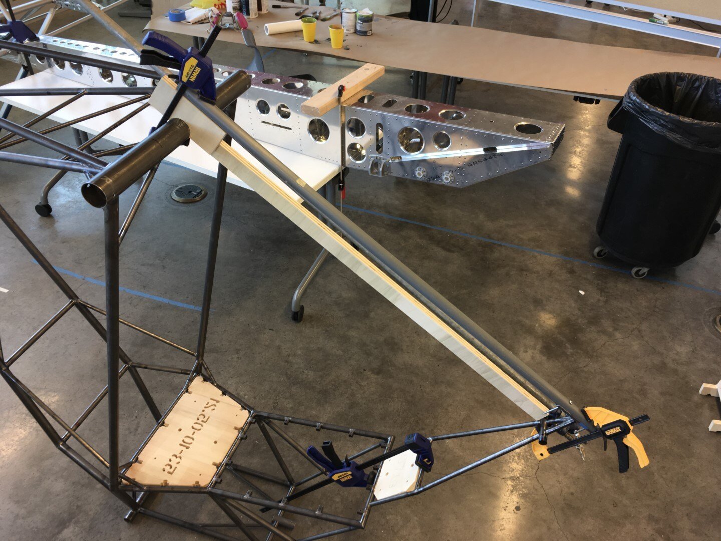
Next up is the Instrument Panel sub-assembly. More tooling helps to locate the placement of the instrument panel with respect to the rest of the frame.
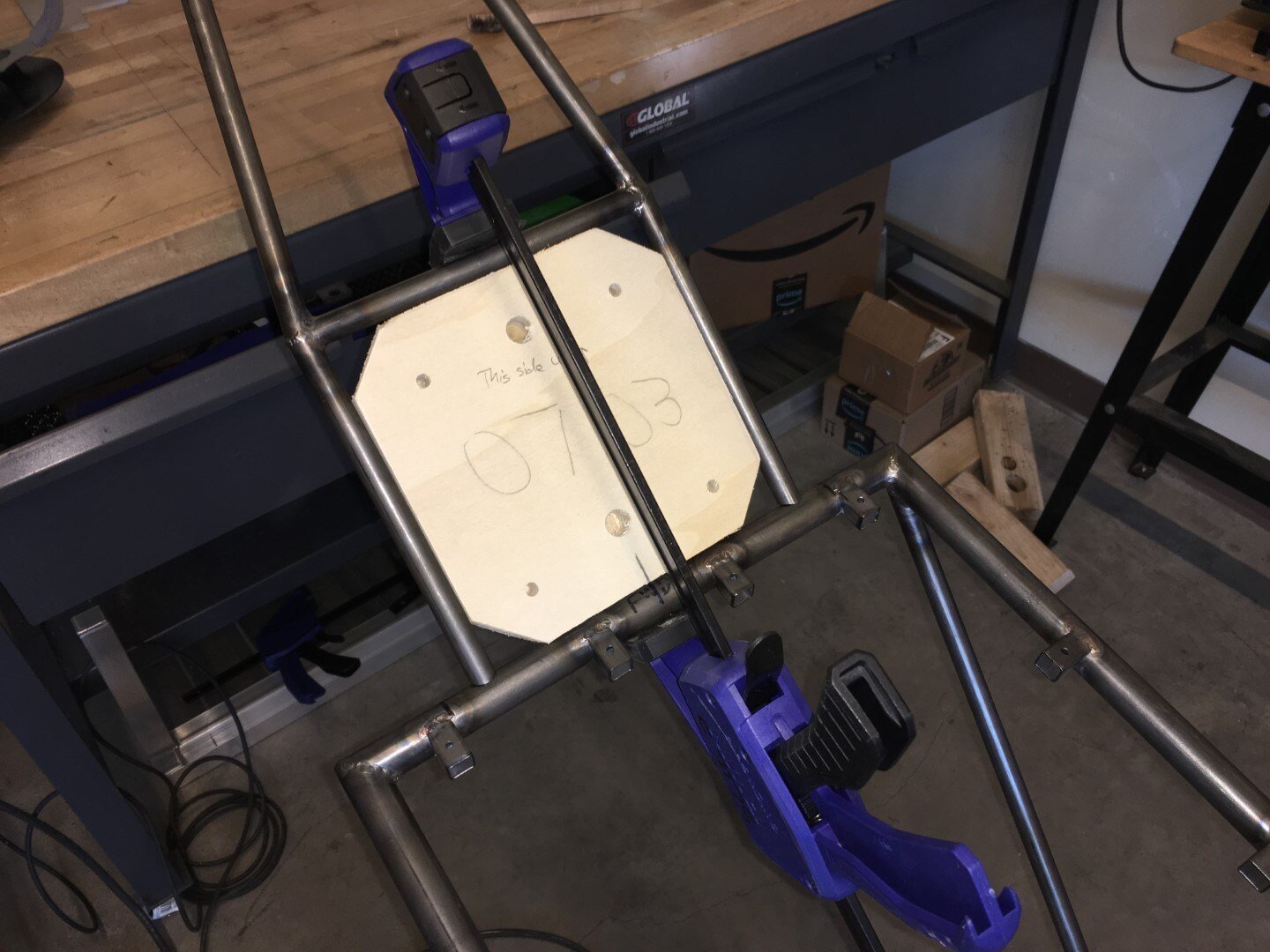
The bottom end of the instrument panel is clamped to the front end of the pilot seat. The plywood jig is inserted to ensure proper spacing between the legs of the instrument panel. We then measure left and right to ensure that the instrument panel is centered on the frame.
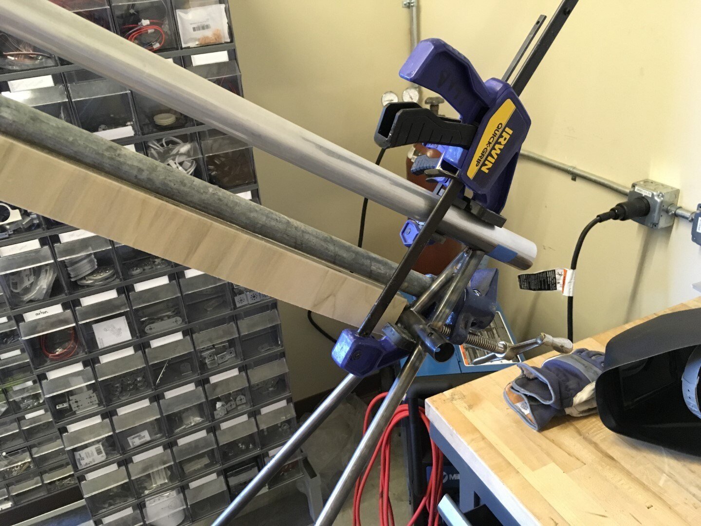
The 1" tube acts as a temporary keel that is placed into the keel saddle which will be welded to the top of the instrument panel.
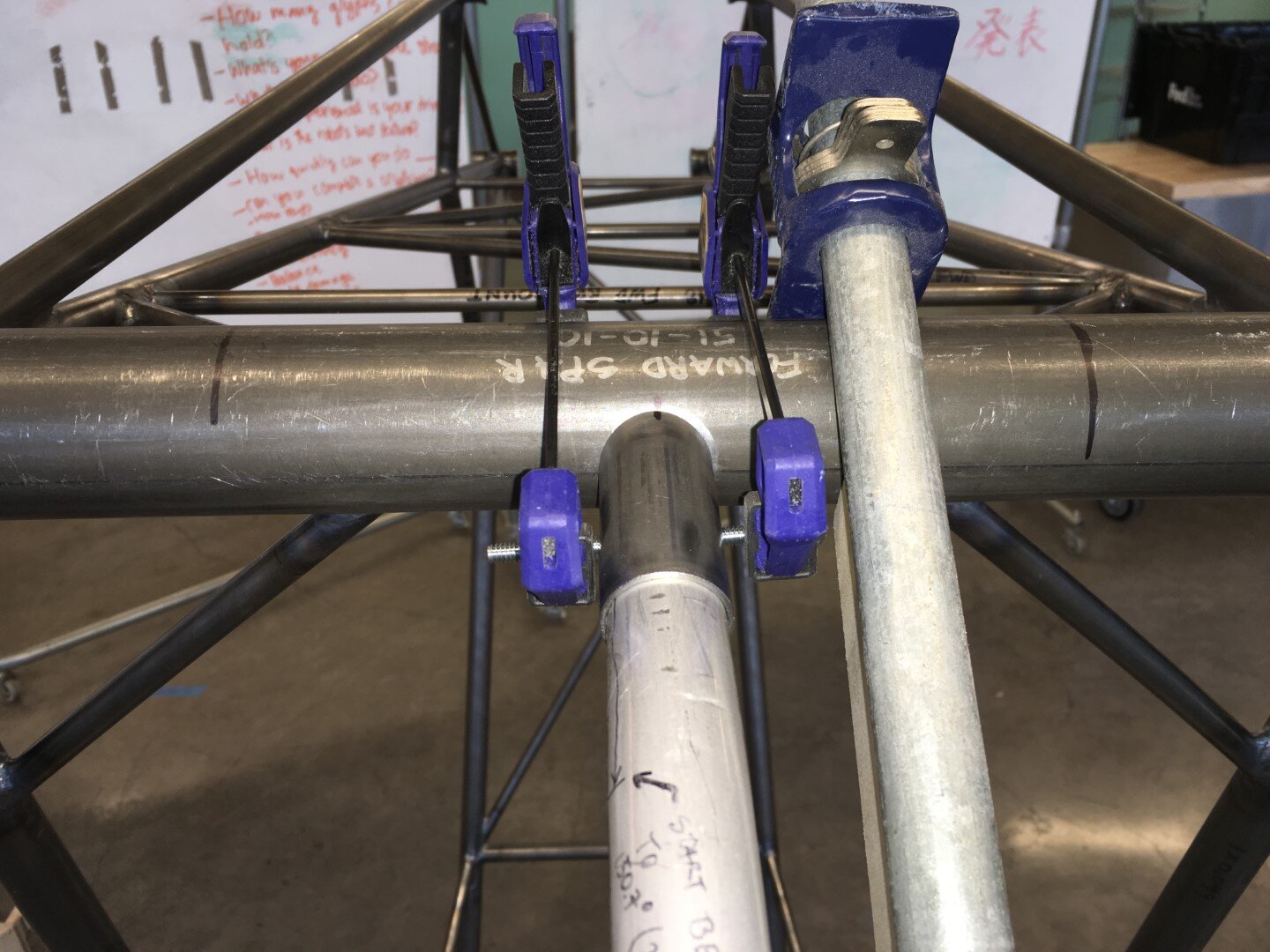
Next up is the Forward Spar Keel Pocket. The 1" aluminum top keel is used to align the pocket prior to welding.
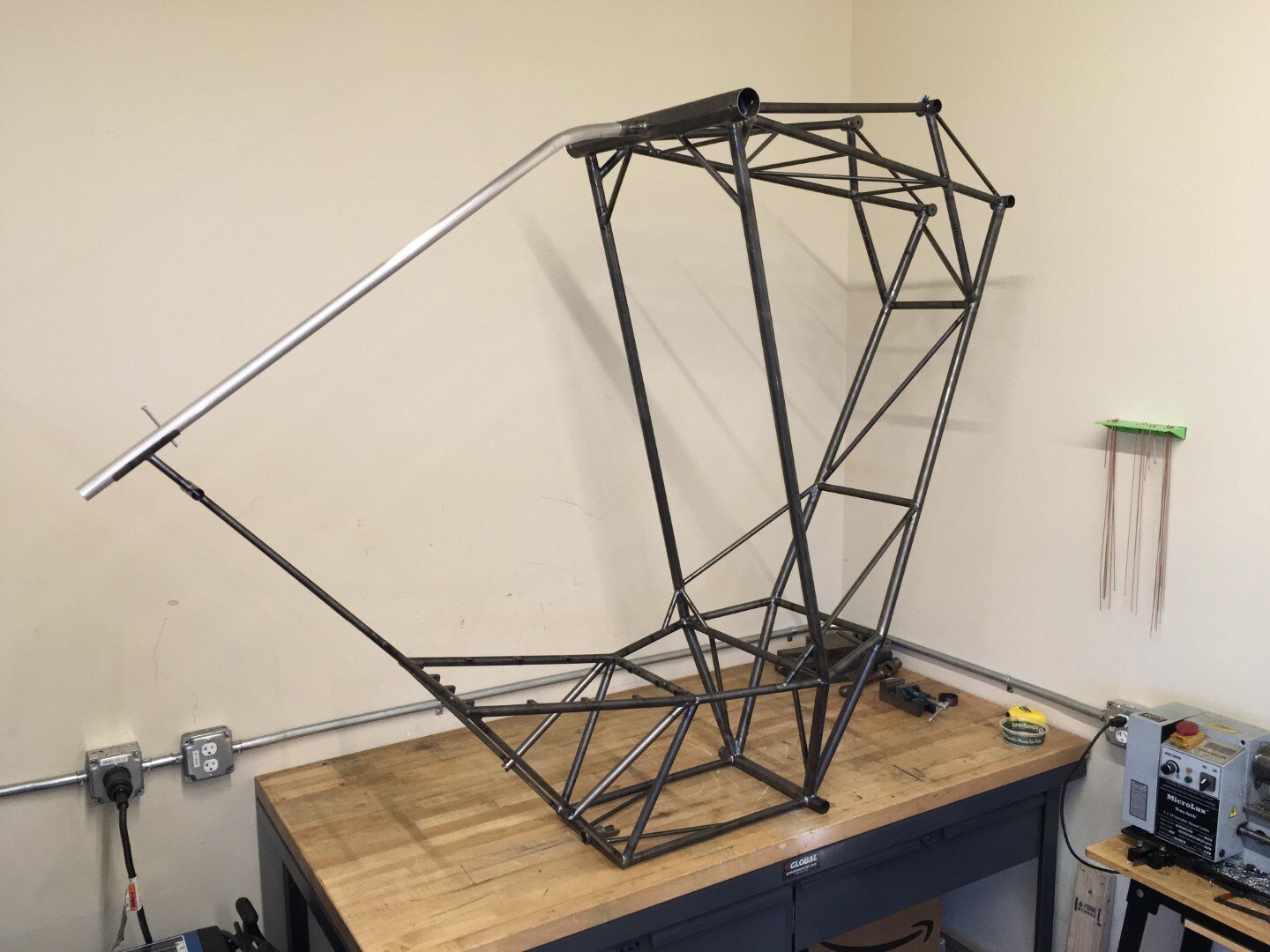
Here's what the fuselage frame looks like to date. The top keel will most likely have to be replaced as the bend radius on the existing part is not quite right. We are currently working on creating tooling that will allow us to bend the upper and lower keel accurately per the drawings.
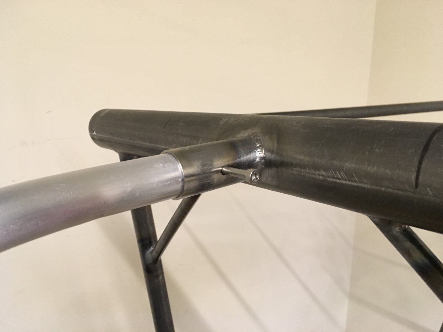
The keel socket with the top keel fitted and drilled.
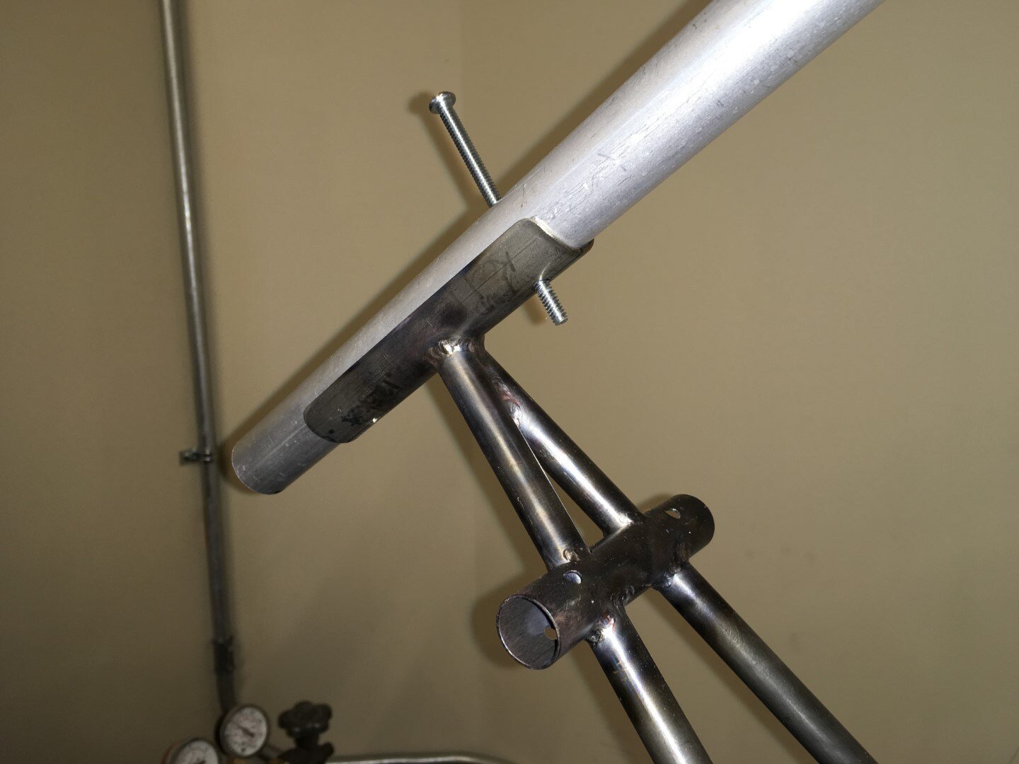
Top keel has been fitted to the keel pocket. It will be trimmed to length such that it reaches about mid-span of the keel pocket. Later the lower keel will be connected using a splice tube.
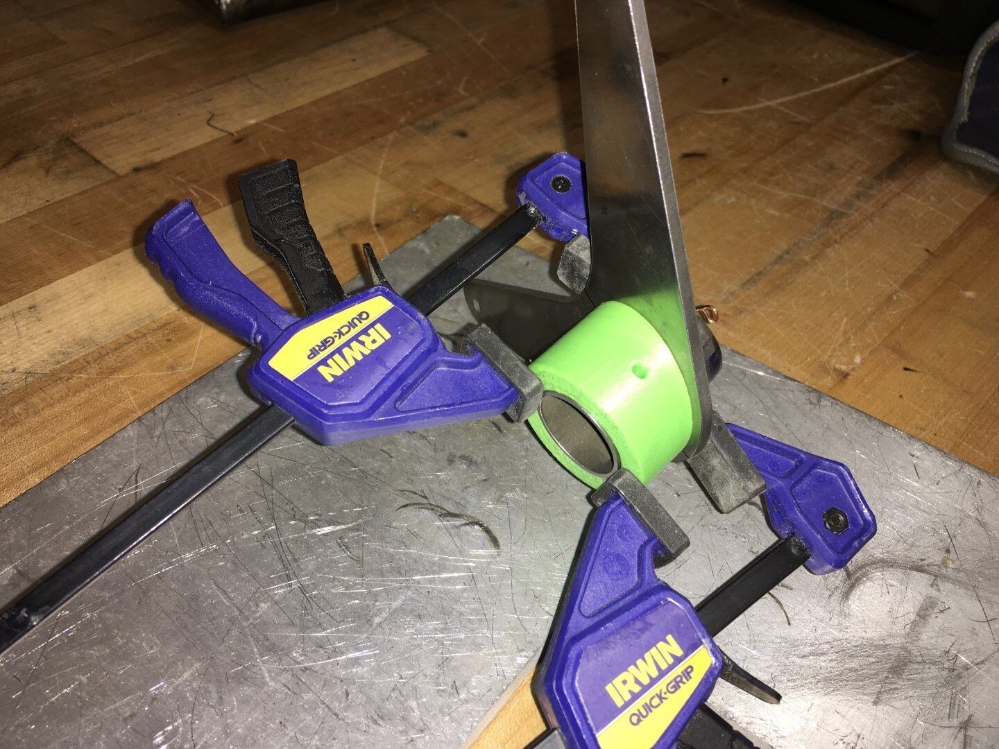
This is the Aileron Aft Bellcrank prior to welding. It consists of the bellcrank cut from 4130 plate which gets welded to a small length of tube. The interface angle is 15 degrees from perpendicular so we designed and printed a sacrificial jig to accurately hold the two parts in place during tacking. The spot welds had to be fast as the heat would quickly propagate to the PLA plastic.
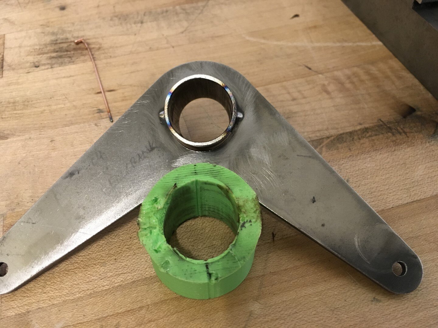
The 3D-printed tooling lasted just long enough to get the tacks into place.
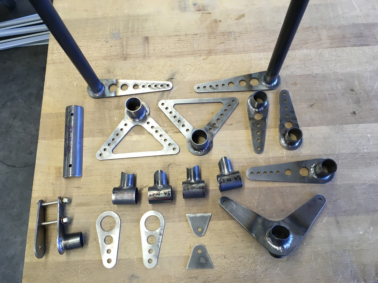
Here's an assortment of some of the fabricated flight control parts.
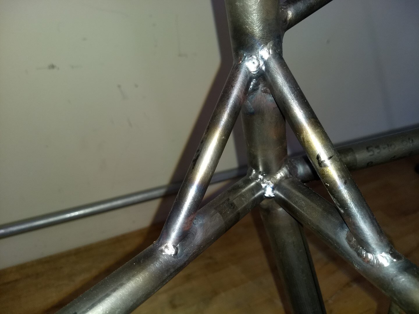
Seat braces are added here.

Instrument panel welded to the pilot seat.
